|
 |
NEC-SIRCS-JAPAN-RC5-SAMSUNG compatible, multiprotocol infrared remote control.
Replaces up to
6
existing remote controls into one.
With manual learning function, LED display and/or LCD.
2V6-3V2, low power (sleep function)
More protocols will be added later if needed (DENON, DAEWOO,
MOTOROLA, RECS80.)
Components:
PIC16LF877-04/L (4Mhz PLCC Package), 24LC256 EEPROM (low
power), 74HC148 encoder (SMD), optional Nokia 3310 graphic LCD (LPH-7779), IR
LED, 5 optional LEDs, TSOP34836 IR receiver (low voltage)
All parts are available in our
online shop
Schematic & pcb (Eagle 4.11e), source code
(CCS) and hex file available.
More pictures.
|
Circuit explanation:
The main component is of course the
PIC16LF877-04/L processor. Its 8K program ROM handles all inputs, outputs, timings and so
on. There are six modes: SLEEP, IDLE, TRANSMIT, RECEIVE, BACKUP & RESTORE.
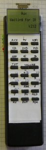
There are two displays available: LED and/or LCD. So
you can choose freely which one suits you best. Naturally, the Nokia LCD gives
us much more details as we will see further on.
| LED display |
LCD |
| LED symbols used: |
"1"= LED on. "0"= LED off. |
 |
 |
| |
|
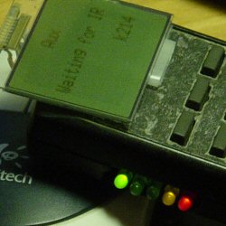
| LED order: (from right to
left) |
LED1, red (PROGRAM) |
| LED2, yellow (SPECIAL) |
| LED3, green (ADDRESS2) binary MSB |
| LED4, green (ADDRESS1) binary |
| LED5, green (ADDRESS0) binary LSB |
| |
|
| Example: "11001" |
means PROGRAM & SPECIAL active on ADDRESS1. |
| Power consumption is only a couple of
microamps in sleep mode !! The circuit is powered by two AAA
batteries (HR03) These may be rechargeable types. The voltage can drop as low
as 2,5V. The battery life is several months (although NI-Mh batteries lose 1%
of their power each day!)
Sleep mode is activated automatically after 20 seconds of inactivity
(no button pressed in idle mode.)
|
|
|
mode |
consumption at 2V6 with
Low Current-LEDs |
consumption at 2V6 with
NOKIA LCD |
| |
|
|
| sleep |
1,2 to 2 µA (!) |
1,2 to 2 µA (!) |
| idle |
1,3 to 1,5 mA |
1,3 to 1,5 mA |
| transmitting IR |
11 to 17 mA |
9 to 13 mA |
| receiving IR |
2 to 10 mA |
2 to 2,2 mA |
| backup or restore |
5 mA |
2,7 mA |
|
|
All user data is stored in the 24LC256 i²c EEPROM. It contains 32768
bytes (8 pages of 4096 bytes.) That's plenty! Pages 0 to 5 (0x0xxx to 0x5xxx)
each contain data from the six devices (Aux, TV, Hifi, CD, DVD, Video) we are
able to use. Page 6 is unused, page 7 stores all configuration data (f.e.
which key is assigned to "PROGRAM" or to the device "DVD"...)
A maximum of 32 keys (4 columns by 8 rows) are supported. We have six
fixed DEVICE SELECT keys (Aux, TV, Hifi, CD, DVD, Video), 1 fixed
PROGRAM key , 1 fixed ENTER key. These eight fixed keys have to be
programmed at the first power up (LCD shows "key init" "Program key?", LEDs
show "01000") See more below. There are a maximum of 24 free COMMAND keys
for each one of the six devices. Each free command key is protocol-free, this
way we can mix protocols inside each device page.
RB4..7 are outputs to the four key columns. RB1..3 are inputs
coming from the 8-bit HC148 encoder.
Whilst in sleep mode, pressing one of the keys on the key-matrix
awakes the processor. The HC148, GS output which goes to to the PIC interrupt
INT/RB0, goes low each time a key is pressed.
Also nice: the last device selected is stored in EEPROM. So, even unpowered,
the circuit will keep all settings & data safe. You can even make a complete
backup or restore of all data ;-)
The IR receiver TSOP34836 (output comes low when a IR burst of
around 36KHz detected) is powered only in program mode. The receiver takes only 0,7 mA
but it's still worth disabling while unneeded. More details about protocols & waveforms
below.
For IR transmitting, there is of course an IR LED. It is boosted
by a BC639. When enabled, it sends out a burst of 37,1 kHz generated by
the processor.
But, as you have guessed, all the rest is program code. More info under "source
code explanation" below.
|
Schematic: right-click & "save picture as" for
full resolution or (recommended) download the eagle-file below. |
 |
Part List (Bill of material):
here.
Main component list & interconnections:
Overview here.
|
Supported protocols:
These five protocols are currently supported. Of course, each have their
own structure: frequency, number of data bits, timing, start & stop bits. Check the table on the right and the waveforms details below.
Protocol waveforms: full details here.
|
|
| # - protocol name |
kHZ |
start bit |
data bits |
stop bit |
| |
|
|
|
|
| 2-NEC |
39,2 |
1 |
32 |
1 |
| 4-SIRCS |
40 |
1 |
12 |
- |
| 5-RC5 |
36 |
1 |
12 |
- |
| 7-JAPAN |
32 |
1 |
48 |
- |
| 8-SAMSUNG |
39,2 |
1 |
32 |
1 |
| |
|
|
|
|
|
|
Notes:
|
Key-Matrix |
EEPROM Resistor Pull-ups |
IR Receiver TSOP34836 |
IR LED |
|
Has a maximum of 4 columns and 8 rows. Unused column connections should be
left unconnected. Unused row connections must be grounded. You could rip one from an old remote.... |
The pull-ups are 10k here. A value around 1k8 is more common, but power
consumption is reduced significantly with 10k... |
This low voltage component is made by Vishay. It works well at 2V6.
Whereas a regular IR receiver (TSOP 1736 or 1836) operates at 5V!
The 36 kHZ one handles all supported protocols fine. |
A standard IR LED is ok. We can run a fairly high current through it, because it
is only lit for a very brief time. Hence the 4R7 at T1's emitter.
|
|
PLCC PIC16LF877-04/L 4MhZ |
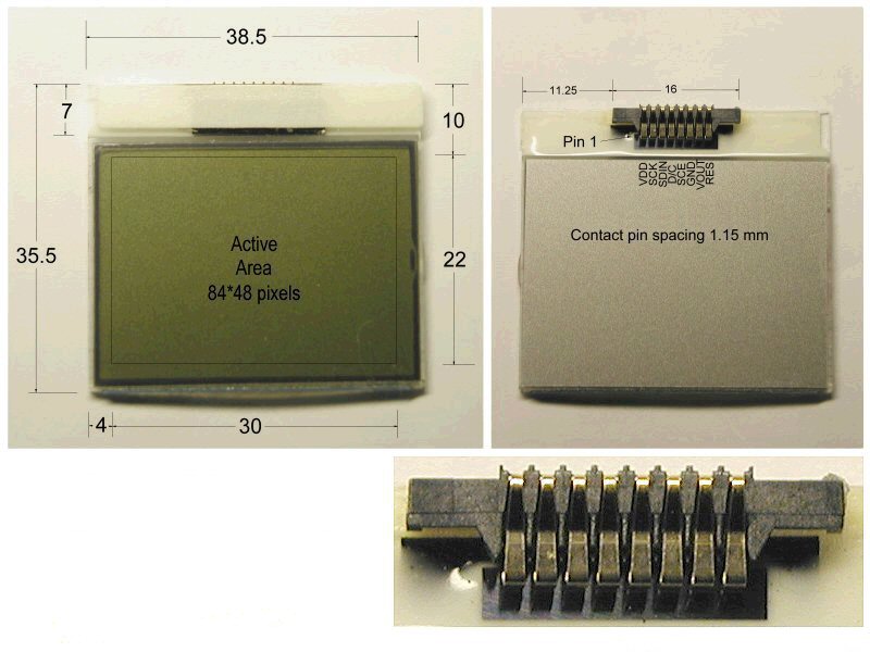
Nokia 3310 LCD (LPH7779) |
5 Display-LED resistors |
LED or LCD display ? |
|
PLCC has been chosen only for its reduced size.
This chip is functionally fully compatible with a 16F877 DIL (40 pins.) |
This is a fine graphical LCD. It is also quite cheap, so i just love using it...
It has an incorporated controller
PCD8544
and takes around 0.2mA only. Voltage must be between 2V5 and 3V2. |
The five 3mm display-LED's current must by delimited by a resistor.
Values are 56R for normal (10mA) LEDs and 300R for low current
(2mA) LEDs. Calculate others
here. |
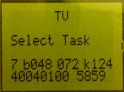
You can choose between the LEDs or the LCD for displaying info.
The LCD can display very detailed IR info: protocol number (- to 8),
number of data bits, elapsed program cycles, key-number pressed
last & all data bit values. |
Menu & display structure:
|
Here's some useful info about how to program keys & how to
perform several tasks listed on the right.
All details here. |
Device select |
| IR transmit mode |
| IR receive & program a command key |
| IR Details ON/OFF: |
| Soft reset: |
| Backup mode: |
| Restore mode: |
| Sleep mode |
| Idle mode |
| Init mode: |
Software flow chart:
coming soon...
Downloads:
WARNING:
may not be
duplicated for any commercial use whatsoever without explicit consent from the
author
(c)
Michel Bavin
|
Hex file:
011_v30_hex.zip, july 25, 2004: 011_30.hex (to program the PIC) |
|
Source code:
011_v28_c.zip
(CCS compiler), february 25, 2004 : 011_28.c
(with include
files 16f877_mb.h / 24256_mb.c / ir_read_mb / nokia_3310_mb.c)
|
|
Schematic:
011_02_sch.zip
(Eagle 4.11e), february 26, 2004: 011_02.sch
and (important) this library file
microchip_mb.lbr
(to be copied to the *\eagle*\lbr directory. This is an altered package
for the PIC)
|
|
PCB:
011_02_brd.zip
(Eagle 4.11e), march 19, 2005: 011_02.brd
Get this page as PDF |
PCB screenshots:
real size= 48,6 x 39,7 mm or 1,90 x 1,55 inches.
| All layers (top view) |
Top copper layer |
Bottom copper layer |
|
 |
 |
 |
Source code explanation: (CCS
compiler)
coming soon...
Info & datasheet:
TSOP34836 IR Receiver, low voltage, low power,Vishay.
Graphic LCD module type
LPH7779 (NOKIA 3310 LCD)
and its integrated controller
PCD8544.
More IR protocols related
info.
Tools:
Check out our development
tools
page.
This project is made with the PCWH
CCS
compiler ($425,-). You can install Microchip's free
MPLAB IDE with it to get things going smoothly.
Programming of the PIC was done with
IC-Prog on a
PIC-
programmer built from Electronique pratique nr 253 (january 2001).
Eagle
can be used for the schematic & PCB layout. The
free version
should be ok for this
design.
Projects Home