Weather station

Get this page as PDF

Projects Home


Weather station with pressure reading, relative humidity, indoor & remote outdoor temperature display.

Both Celsius or Fahrenheit & mbar/hPa or mm Hg  supported. With calendar & clock. Easy 3-button user-menu. 42 hour-history display (curve). Auto-memory & display of all high and low-values.

PIC 18F452 running at 4 MHz, power saving sleep mode. Sensors are only turned on when needed.

All parts are available in our online shop.

Schematic & pcb (Eagle 4.11e), source code (CCS) and hex file available. Updated on May 6, 2006.

Future developments: fully solar powered.


Circuit explanation:

  Now this was a huge project! All sensors had to be fully tested one at a time, wireless communication had to be perfect, various LCDs were tried. Nevertheless, here's the result: hope you enjoy it!

The circuit may be powered by a small 9V battery, but you'd better take a couple of AA-batteries. A 6-pack will last a several months. Consumption for the base station is around 8 to 9 mA whilst active and only 2 to 3 mA in sleep mode (LCD remains on.) The transmitter takes slightly less.

The receiver (base station) is active during 5 seconds & then goes to sleep for 45 seconds. The transmitter takes a nap every 30 seconds or so.

Menu mode 
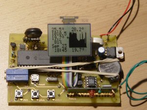
is entered when pushing the "menu" button (what's in a name?) for 1 second. Browsing & value changes are done with the "min" & "plus" keys. When in 
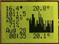
normal mode (like in the picture above), the "min" and "plus" keys can browse through the different histories. All these controls will wake up the processor if it was in sleep mode.

On the left-hand side of the LCD we have (from top to bottom:) Outside temperature, Pressure, Inside Temperature, Relative Humidity, Calendar and Clock.

On the right: High value of the past 42-hours, Bar graph histogram (right is most recent value), Low value.

All sensors are read & LCD (left-hand side) are updated every 50 seconds. Histogram is updated on the hour (e.g. 10h00, 17h00, 22h00,...)

All data is stored in EEPROM and is loaded at power-up. In case of a power failure (or when changing batteries), there will be no data (nor history) lost.

     
MPX 4115A pressure sensor Most expensive part of the project (around € 20,- / $ 25,-), but it's worth it. Output of this sensor is an analogue voltage, which is temperature-compensated! We'll feed this directly to the PIC's 10-bit ADC.

TC77 SPI temperature sensor Nice SPI-sensor in a tiny SO-08 package. We'll use an emulated SPI-mode since we're already using I²C for the RTC (with a DS1307) and the external memory (24LC256), but this works just as well. Resolution goes to one tenth of a degree Celsius!

H1 humidity sensor This sensor's output is a capacitance between 112pF (at 10% RH) and 143pF (90% RH) Its curve is not linear so we'll use a simple table to convert the A/D reading to the correct RH-value. Capacitance to frequency conversion is done with a simple 555 timing circuit. This frequency is fed to the PIC's T1_CLK.

RX+TX433: wireless modules These are cheap modules. They have a quite good range (to 25m indoors and 150m outdoors.) Data size of one packet is 32 bits. Bits 8 (LSB) to 19 (MSB) contain temperature data (BCD). Bit 21 is the minus sign, bit 23 is a low battery warning.


Schematics: right-click & "save picture as" for full resolution or (recommended) download the eagle-file below.

Base-station (receiver)


Remote temperature sensor (transmitter) compatible with HUGER & OREGON SCIENTIFIC remote sensors


Part Lists (Bill of material): receiver and transmitter.


Receiver, calibration:

Pressure calibration Make sure you're using a reliable multimeter, and not a cheap one. First adjust VREF- (PIC RA2, pin 4) to 2V40 with trimmer R9. Then adjust VREF+ (RA3, pin 5) to 4V70 with trimmer R8. At last, do a manual (linear) pressure correction via the menu (see below.) Of course, you'll have to know the current pressure for your area ... but this is just once!
Humidity calibration Is done via the menu (see below). This is a one-time, linear correction.
Temperature calibration No need, the TC77 sensors are fully calibrated.

Receiver, main interconnections:

LPH7779 module 18F452 DIL   various 18F452 DIL
                 
pin # schematic & code symbol pin #   description schematic & code symbol pin #
                 
1 +5v VDD 11,32   i²c SCL SCL SCL, C3 18
2  sclk RD5 28   i²c SDA SDA SDA, C4 23
3  sda RD4 27          
4 d/!c RC5 24   SPI TC77 !CS TC77_CS B7 40
5  !cs RD3 22   SPI TC77 SIO TC77_SIO B6 39
6 gnd GND 12,31   SPI TC77 SCK TC77_SCK B5 38
7 Vout              
8 !res RD2 21   power for mpx4115a MPX4115A_POWER B3 36
          analog from mpx4115a (bar_analog) A1 3
                 
          power for the RX433 module RX433_POWER E2 10
          radio from RX433 module CP1 CCP1, C2 17
                 
          RS232 TX TX C6 25
          RS232 RX RX C7 26
                 
          power for H1-circuit(humidity) RH_POWER B4 37
          frequency from the H1-circuit (T1_CLK) C0 15
                 
          -- pushbutton key_min B2 35
          ++ pushbutton key_plus B1 34
          enter pushbutton key_enter B0 33


Receiver, menu structure:   Receiver, external EEPROM (24LC256P) contents:
History Display Mode:  A0= Tin+Tex+Press+RH    (for address 0x1zzy:) zz=0..41dec: history index table (char 8 bits)
   A1= Tin+Press   y: 0..3dec: Tex UMSB..LLSB (float 32 bits)
   A2= Tex+Press   y: 4..7dec: Pressure UMSB..LLSB (float 32 bits)
   A3= Tin+Tex+Press   y: 8..11dec: Tin UMSB..LLSB (float 32 bits)
Time Set:  B0 to B7 = set calendar & clock   y: 12dec: Relative Humidity (char 8 bits)
Temperature output:  C0= Celsius   0x0003= temp_outp= Temperature notation (0= Celsius, 1= Fahrenheit)
   C1= Fahrenheit   0x0004= press_outp= Atmospheric Pressure notation (0= mBar/hPa, 1= inHg)
Pressure output:  D0= mbar / hPa   0x0005= p_corr= Manual Correction for Pressure (0..255dec)
   D1= inHg   0x0006= rh_corr= Manual Correction for Relative Humidity (0..255dec)
Pressure correction:  E= manual pressure adjust   0x0007= hist_index= current history index (0..41dec)
Humidity correction:  F= manual humidity adjust   0x0008= hist_sel= history selection(0..3dec) (Tex, Press, Tin, RH)
Clear history:  G= Clear EEPROM history
Exit menu:  

Wireless temperature sensor waveforms:

Full timing details of the transmission protocol:

Total transmission example: (black colon is signal high.) data MSB is on the utmost right.


Downloads:

 WARNING: may not be duplicated for any commercial use whatsoever without explicit consent from the author (c) Michel Bavin


for the base-station (receiver:)

Hex file: 012_v32_hex.zip,  September 12, 2004: 012_32.hex (to program the PIC 18F452)  

Source code: 012_v32_c.zip , September 12, 2004 : 012_32.c (CCS compiler)

  (with include files 24256_mb.c / ds1307_mb_v1.c / lph7779_v3.c / menu_012.c / rx_radio_012.c)

Schematic: 012_base_sch.zip , September 9, 2004: 012_base.sch (Eagle 4.11e)

 (with these library files:  pic18f4x2.lbr and ic-package_mb.lbr  (important: copy these to your eagle\library directory)

PCB:  012_base_brd.zip, September 9, 2004: 012_base.brd (Eagle 4.11e)


for the remote temperature sensor (transmitter:)

Hex file: 012_v105_hex.zip,  May 6, 2006: 012_105.hex (to program the PIC 16F84A)  
Source code: 012_v105_c.zip , May 6, 2006: 012_105.c (CCS compiler)
Schematic: 012_transmit_sch.zip , September 12, 2004: 012_trans.sch (Eagle 4.11e)
PCB:  012_transmit_brd.zip , September 14, 2004: 012_trans.brd (Eagle 4.11e)


Get this page as PDF


PCB screenshots:


Base station (receiver:)


Remote transmitter (outside temperature:)


Info & datasheet:

MPX4115A pressure sensor from Motorola.  
TC77 SPI temperature sensor (Microchip.)  
H1 humidity sensor (Philips.)  
RX+TX433: wireless modules (Velleman)  
DS1307  i²c RTC  
24C256 i²c EEPROM  
MCP120-450D brownout detect (Microchip)  
Graphic LCD module type LPH7779 (NOKIA 3310 LCD) and its integrated controller PCD8544.  

Tools:

Check out our development tools page.

This project is made with the PCWH CCS compiler ($500,-) You can install Microchip's free MPLAB IDE with it to get things going smoothly.

Programming of the PIC18F452 was done with the excellent Tiny PIC bootloader, through the RC6 & RC7 pins. But you'll need a regular PIC programmer to write the PIC the first time with...

The remote transmitter has software RS232 on pins 9 (RB3,TX) and 10 (RB4,RX) for debugging only.

Eagle 4.11 was used for the schematic & PCB layout. 


Projects Home