|
 |
|
Here is an example of how to interface a
PIC18F452 to a PC via the USB port.
The windows-pc (98, Me, 2000, XP, 2003) runs a
program (C#
application, Microsoft Visual Studio .NET 2003) to communicate with the
USB interface, which transfers data to and from the PIC18F452.
Many thanks to
FTDI to deliver royalty-free drivers (FTD2XX.dll) and to
KOPF to
develop the needed library (AID.dll)
All parts are available in our
online shop.
Schematic (Eagle 4.11e),
PIC source code
(CCS) ,
PIC hex file, C# code and application available for
download. |
Circuit explanation:
| |
PIC example (18f452) <
> USB interface (FT245BM) <
> PC program (C# application) |
|
PIC example (18F452:)
The PIC captures the ambient temperature with a
SPI sensor
TC77. Its value is then transferred to the USB-interface.
USB interface
(FT245BM:)
The USB interface
will have to be recognized as a device by Windows. Basically, there are two
ways of doing this. Either with a VCP (Virtual COM
Port) or with a D2XX (Direct) driver. We will use the D2XX driver here
for its high speed. It is more complicated to start up than VCP, but
why not going the extra mile?
The FT245BM chip
comes with a fixed VID (0403) and PID
(6001). We can override this with our own VID (ECDE), PID (0001),
our own Product Description (TechDesign USB Device 017) and serial number
(FEDC0001). These settings are stored in an external SPI EEPROM
93C46. To program these settings,
FTDI made a utility called
MProg EEPROM
programming utility.
When plugging in
for the first time and with a blank (or without) EEPROM, you will notice that the
interface is seen as "USB device" and after its
driver
is installed, it will be recognized as a "FTDI FT8U2XX Device". Now we
can program the EEPROM with our custom settings. To do this, run
MProg,
open the file
017_USB_id.ept
and program (choose "Device", then "Program"). After this, unplug the
interface briefly and plug it in again. It will now be recognized as a "TechDesign USB Device 017".
Acknowledge a couple of times to install it and you are done.
Note that this
project will also work without an EEPROM, but in that case you will have to
make do
with the fixed VID & PID.
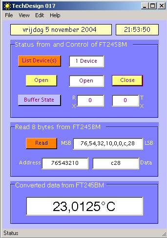
PC program (C# application:)
A dll file
is
performing the communication between the C# application and our USB-interface.
It must be placed in the same directory as the exe-file below.
Acknowledgements to
KOPF
for
providing this dll and the example "USBTransfer.exe" on which this application
is based.
The C# application can be run on any
Windows 98, Me, 2000, XP, 2003 platform. It will show the temperature reading
captured with the PIC (see above). Here is a
quick link
to its main form. Download the
msi
(Microsoft installer file) below to install the application.
You need to have
Microsoft .NET Framework 1.1 (or higher) installed to
be able to run
the executable.
|
Schematics: right-click & "save picture as" for
full resolution or (recommended) download the eagle-files below. |
|
PIC example (18F452) |
 |
|
USB interface (FT245BM) |
 |
Main connections:
|
|
|
P1 PINHEAD, FT245BM |
PIC 18F452 |
|
P1 PINHEAD, FT245BM |
PIC18F452 |
| |
|
|
|
|
| 1= D0 |
RD0, pin19 |
|
2= +5v |
VDD, pin11 & 32 |
| 3= D1 |
RD1, pin20 |
|
4= !RSTOUT |
not connected |
| 5= D2 |
RD2, pin21 |
|
6= GND |
GND, pin12 & 31 |
| 7= D3 |
RD3, pin22 |
|
8= !PWREN out |
RB2, pin35 |
| 9= D4 |
RD4, pin27 |
|
10= !RXF out |
RB6, pin39 |
| 11= D5 |
RD5, pin28 |
|
12= !TXE out |
RB5, pin38 |
| 13= D6 |
RD6, pin29 |
|
14= WR in |
RB4, pin37 |
| 15= D7 |
RD7, pin30 |
|
15= !RD in |
RB3, pin36 |
|
|
The 16-pin pinhead allows fast prototyping development.
This way you
do not need to buy a brand new FT245BM for each and every development you make.
This means that one pinhead at the interface-side and one at the PIC-side
are needed.
Connection between two pinheads is made with regular flatcable.
|
| |
|
|
|
Downloads:
right-click & "save as"
WARNING:
may not be
duplicated for any commercial use whatsoever without explicit consent from the
author
(c)
Michel Bavin
|
PIC example |
|
Schematic:
017_pic_01.sch
(Eagle 4.11e), October 24, 2004 and
eagle_lib.zip (Important: copy
these to your \eagle\lbr directory). |
|
PCB:
017_pic_01.brd
(Eagle 4.11e), October 24, 2004. |
|
CCS
Source code:
pic_017_04.c
, November 7, 2004. |
|
PIC
Hex file:
pic_017_04.HEX (to program the PIC) November 7, 2004. |
| |
|
USB interface |
|
Schematic: 017_ft_01.sch
(Eagle 4.11e), October 24, 2004 and
eagle_lib.zip (Important: copy
these to your \eagle\lbr directory). |
|
PCB: 017_ft_01.brd
(Eagle 4.11e), October 24, 2004. |
|
D2XX (Direct) Windows
driver:
FTD2XX_TechDesign_driver.zip
|
|
USB in-circuit EEPROM
programming utility:
MProg and
017_USB_id.ept
(open in MProg and program the EEPROM with the custom VID and PID). |
| |
|
Windows
Application |
|
C# source code: Csharp_017v12.zip (Visual Studio .NET 2003), November
11, 2004. |
|
Windows executable & DLL: TechDesign_017v12.msi (complete application install and shortcut on your desktop)
November 11, 2004.
Important Note: You need to have
Microsoft .NET Framework 1.1 (or higher) installed to get the executable
running. |
Get this page as PDF
Info & datasheet:
Screenshots:
|
PCB USB interface (FT245BM) |
|
Windows application |
|
 |
|
 |
|
|
|
PCB PIC example (18F452)
|
|
 |
Tools:
Check out our development
tools
page.
The Windows application was made
with
C#
(Microsoft
Visual Studio .NET 2003).
The PIC code was made with the PCWH
CCS
compiler ($500,-); you can install Microchip's
MPLAB IDE (click on the link and you can get it for free) with it to get things
running smoothly.
Programming of the PIC was done with
the excellent
Tiny PIC bootloader, through the RC6 & RC7 pins. However you will need a regular
PIC programmer to
write the PIC the first time with...
Eagle 4.11e
was used for the schematic & PCB layout.
Projects Home