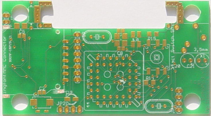
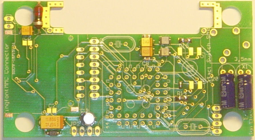
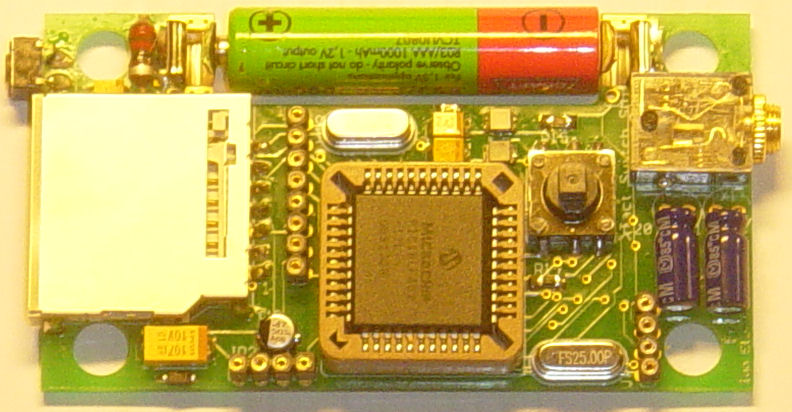
PCB, top view (picture)
These parts will fit on this side of the PCB:
- PIC microcontroller 18LF452 I/L
- 20 and 25 MhZ crystals,
- Micro joystick for user controls
- Connectors to the LCD and RS232.
- MMC/SD Card socket
- Some coils, a diode, resistors and capacitors.
size = 82 x 45 mm or 3"29 x 1"77
Double sided and 100% tested PCB with plated-through-hole connections.
All holes are drilled already.
PCB version: October, 2008.
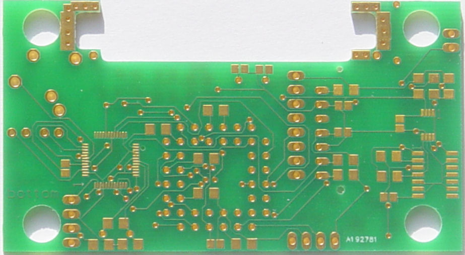
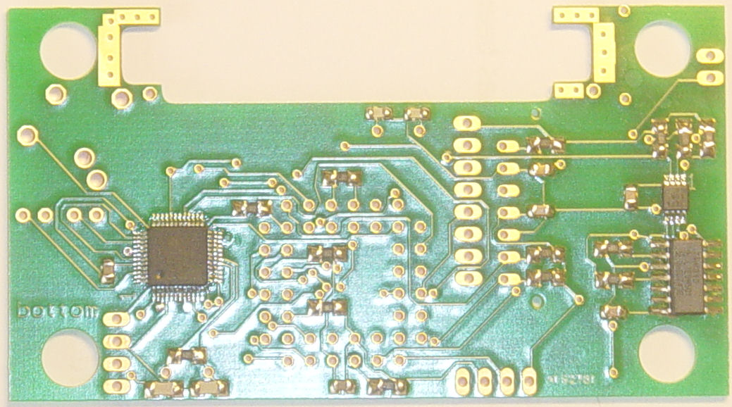
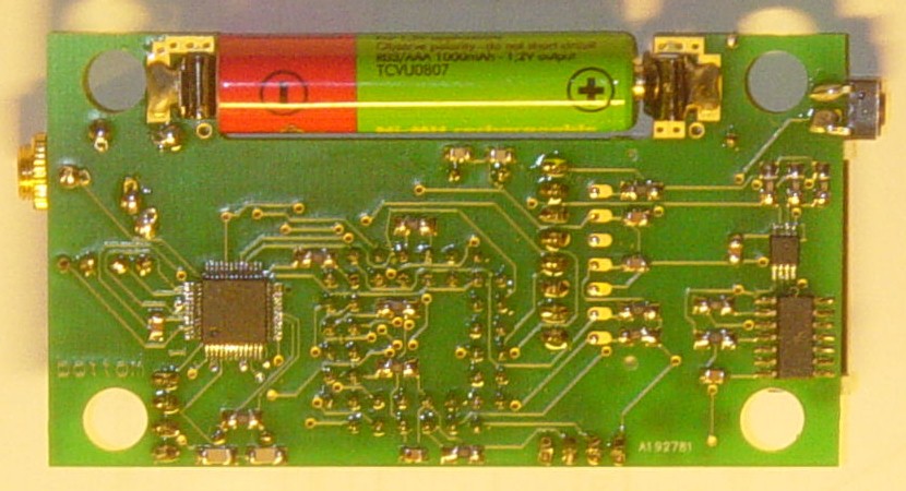
PCB, bottom view (picture)
These parts will fit on this side of the PCB:
-
VS1002D-L MP3 decoder
-
MAX1674 step-up DC-DC converter
-
74HC04 for the on/off circuit
-
Some resistors and capacitors.
Solder these three parts very carefully. You'll probably need a lot of patience, so take your time to do it. Due to the small sizes of the chips, this is by far the most difficult part of the whole construction.
Use a magnifying glass and a very fine soldering iron to do the soldering. First pre-solder the chips by adding a bit of solder to all pins. Then place the chips onto the PCB and make sure pin 1 is well placed. The purple arrows on the drawing point to pin 1 of the chips. On the PCB, there is a small "1" etched.
In case you make a short (with the use of too much solder for example) Stay cool (!) and then desolder with 3S-WICK desoldering braid.
Resistors: (with on-part values)
- 3x 2K2 SMD (222) or (2201)
- 6x 10K SMD (103) or (1002)
- 4x 100k SMD (104) or (1003)
- 1M SMD (105)
Capacitors:
- 2x 22pF SMD
- 2x 33pF SMD
- 6x 100nF SMD
Have a look here if you need some additional help.
Use some PCC (printed circuit board cleaner to get rid of the flux.)
Step 3: PCB top (drawing)
2 Resistors, 2 capacitors and 1 diode.
Resistors: (with on-part values)
- 2x 10K SMD (103) or (1002)
Capacitors:
- 2x 100nF SMD
- skip the two capacitors on the left (leave open)
Diode:
- MBR0520LT1 SMD Schottky diode (cathode marked by white insert and closest to the "B" of the "B2E" marking)
Coils:
- 2x 10µH SMD
- 22µH radial (tru-hole: solder on both sides)
Electrolytic capacitors:
- 0,47µH SMD
- 3x 33 or 47µF SMD (+ is marked by a polarity band.)
- 100µF SMD (+ is marked by a polarity band.)
- 2x 100µF axial (tru-hole: solder bottom side only)
Crystals:
-
20MhZ (tru-hole: solder bottom side only)
-
25MhZ (tru-hole: solder bottom side only)
TACT Micro-Joystick SMT
SIL-strips: (tru-hole: solder bottom side only)
-
4-pin strip JP1 (for future MIC-recording support)
-
4-pin strip JP2 (for RS232 communication)
-
8-pin strip (for Nokia 3310 LCD)
- MMC/SD connector: 2 small knobs fit into the pcb to get the connector firmly placed. Then solder the 7 pads (top only.) Then solder the 3 corners.
- 44-pin PLCC socket: solder bottom only, but have its orientation right: the arrow (pin 1) has to point to the right.
- 3,5mm headphone connector: Bend the contacts towards the PCB and solder bottom only.
- TACT ON/OFF pushbutton: solder both sides.
- Battery contacts: pre-solder these contacts before attaching to the PCB.
Now place the 18LF452 I/L into its socket. A little point marks pin 1, which must be oriented to the right hand side of the PCB.
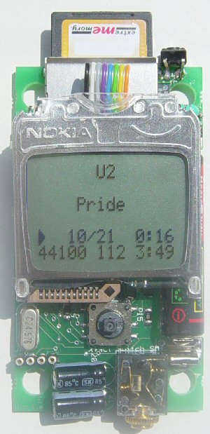
Insert the AAA / LR03 battery, connect your headphones, and plug in the MMC or SD card. Power ON.
You're now ready to rock 'n roll !
The MMC/SD card has to be formatted as FAT (=FAT16) or FAT32 and all mp3-files have to be copied to it all at once.
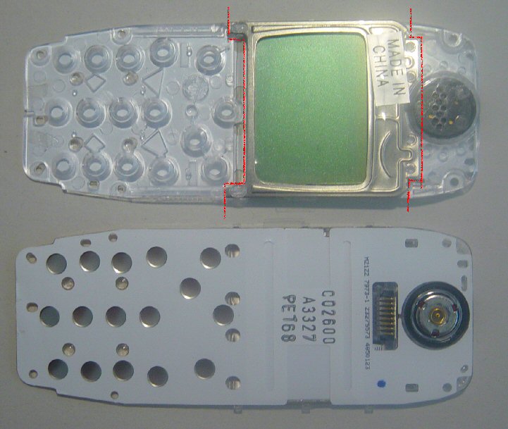
Step 7: Nokia 3310 LCD frame: top & bottom (picture)
Skip this when receiving an LCD with plated connections, and have a look here to connect that one
- Top: remove the little round black speaker (push it out with a needle.)
- Top: remove the "MADE IN CHINA" label.
- Bottom: remove the white plastic cover sheet.
- Top: cut the frame along the red dotted lines. Be careful not to cut into the metal frame.
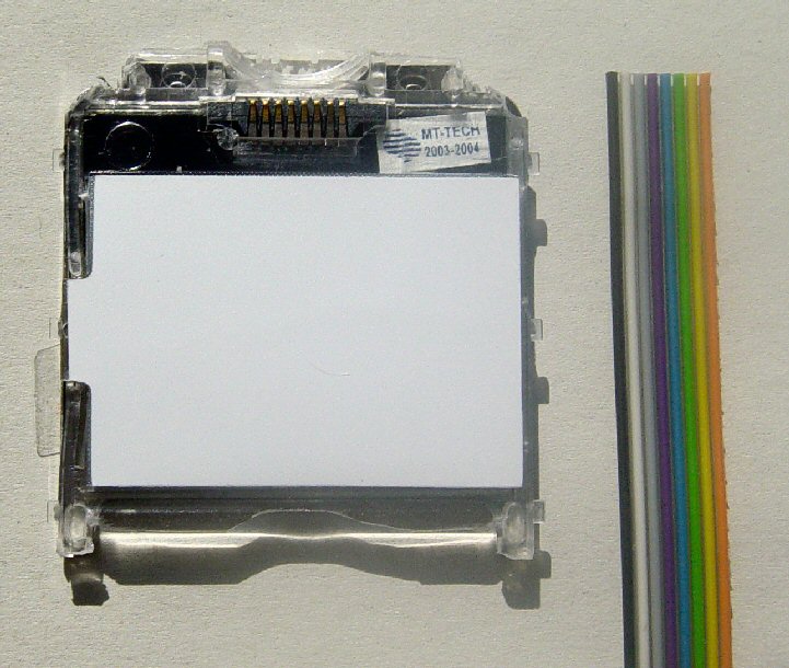
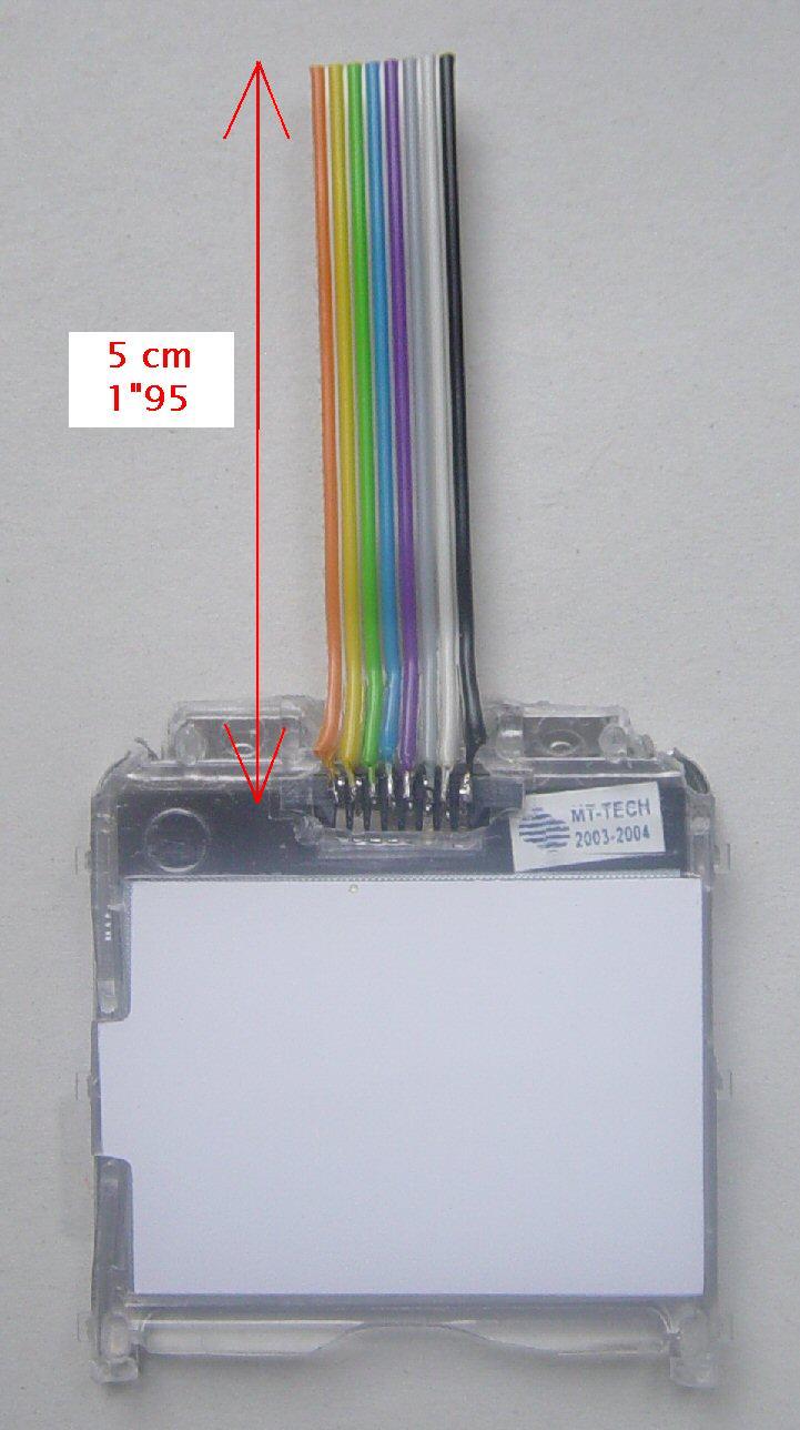
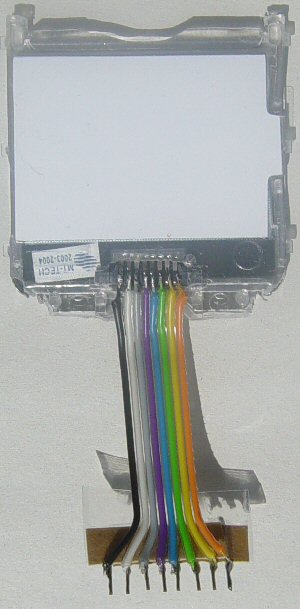
Step 8: Nokia 3310 LCD module: bottom (picture)
- This left picture shows what we have at this stage.
- Now get the flatcable (8-wired) ready.
- Strip the flatcable, twist and pre-solder the wires and cut the ends.
- Pre-solder the LCD-contacts (only topmost side.)
- Solder the flatcable onto the LCD-contacts.
- Now you should have something like on the right picture.
In some cases, the little black LCD-contacts connector is a little loose. This may result in a flickering display. You may tighten this connector by inserting little wooden toothpicks in the corners. Then cut the toothpicks just above the connector.
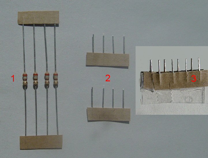
Step 9: LCD connector building (picture)
- Get hold of 4 resistors (on a cardboard strip.)
- Cut the ends of both sides.
- Glue those two ends together. This becomes our 8-pin connector.
- Right picture, solder the 8 LCD-flatcable wires to the 8-pin connector.
A more robust connector can be built by soldering the flatcable to an 8-pin SIL pinhead (instead of the cardboard strip.)
You can also solder the flatcable to the PCB SIL-socket directly.
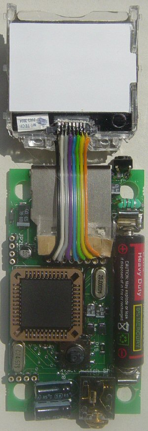
Step 10: LCD connector plugin (picture)
- Plug the LCD-connector into the SIL-socket on the PCB.
- Bend the flatcable carefully. The LCD is now in place.
- In some cases, you'll need to apply a paperclip on top of the module to have a little pressure onto the LCD frame.
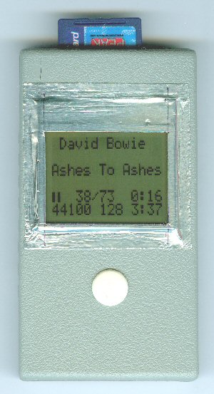
Step 11: PROJECT BOX (picture)
-
In case you bought the project box (around which the player was built): be aware that there are some edges and so to be removed before the player fits into it.
-
You also might want to make the joystick a little longer. I stripped a cheap 3,5mm headphone connector for this, but you might as well put a pinhead in it...
That's it! Have lots of fun building it!