TD-USB-01: ADNS-2620 mouse interface

Get this page as PDF


TechDesign Electronics


Projects Home


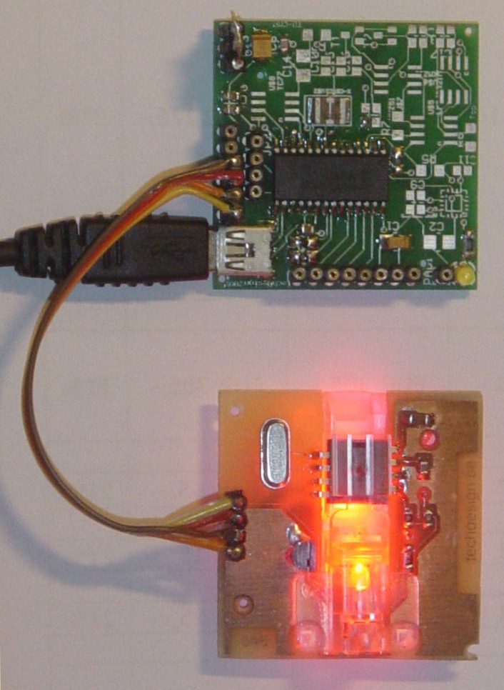
TD-USB-01 interface with mouse sensor board.

This is an example USB project showing how to interface an optical mouse sensor (the ADNS-2620) with a standard XP/Vista computer.

The TD-USB-01 board with a PIC18F2550 communicates with:

  • the PC: USB 2.0 through a mini-B connector.
  • the mouse sensor board: SPI over 4-wire flatcable.

Here are the technical specifications:

  • PC Win XP/Vista interface application with Visual C# 2008 Express: free download.
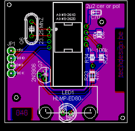
  • TD-USB-01 (green pcb on top) with PIC18F2550 USB HID setup.
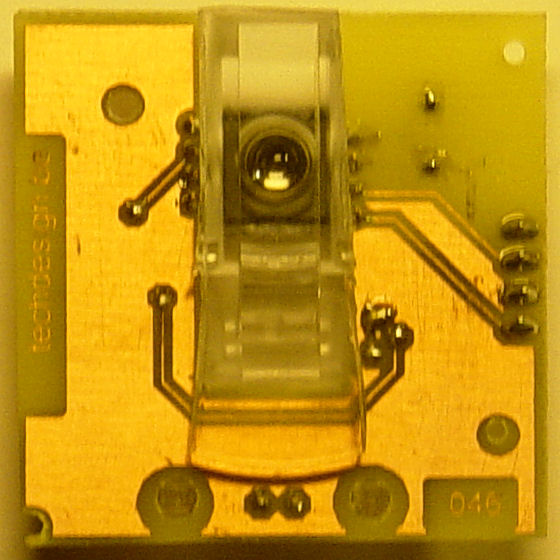
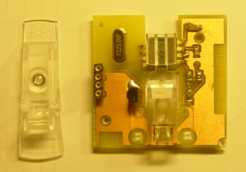
  • Mouse sensor board (046) with ADNS-2620.
  • USB Bus powered, no external power supply needed.
  • ADNS-2620 registers selection stored in the windows registry.
  • Refresh rate from 1mS up.
  • Data bits & bytes details.
  • Real mouse functionality.
  • Sensor CCD 324 pixels: image displayed: 18x18, 6-bit greyscale.
  • TD-USB-01 software is 100% upgradable with a simple RS232 bootloader.
  • RS232 interface for raw data readings.
  • PCB Dimensions: 40 x 41 mm or 1"57 x 1"61

These assembled boards are available from our online shop.

Source code (CCS C and Visual C#) can be purchased separately.


Sensor example Source code (CCS C) , sensor board pcb layout and schematics (Eagle) available. 

Last update: March 28, 2009.

TD-USB-01 (green pcb on top)

Mouse sensor board (046) (bottom pcb, top view)


Mouse sensor board (046) (bottom view)

PC Win XP/Vista interface application with Visual C# 2008 Express


Mouse sensor board: Schematic & PCB: (right click & "save as" to get full resolution)


TD-USB-01: Main Connections:


TD-USB-01 diagram

Header pinouts

Mouse sensor board (046)

JP1 pins

SPI interface


TD-USB-01

JP3 pins

     
1 +5V 1
4 SCK, RB1 2
2 SDIO, RB0 3
3 GND 4
  no connect 5
  no connect 6
 
TD-USB-01: JP2 RS232  
   
1 +5V
2 RX
3 GND
4 TX

Downloads: right-click & save as

 
  WARNING: may not be duplicated for any commercial use whatsoever without explicit consent from the author (c) Michel Bavin, TechDesign Electronics.


 Sensor Board (046): Eagle PCB layout: 046_v002.brd  - Jan. 31, 2009.

 Sensor Board (046): Eagle Schematics: 046_v002.sch  - Jan. 31, 2009.


 ADNS-2620: CCS c source code: optical_mouse_v03.c  - March 27, 2009.

 TD-USB-01:Hex file: 046_v003.hex bootloading for the PIC18f2550  - March 27, 2009.

 Windows interface application setup: 046_app_setup.zip  - March 27, 2009. Written in Visual C# 2008 Express, compatible with Windows XP and Vista.


Get this page as PDF


Info & datasheet:

ADNS-2620
Generic_hid_cs
Microsoft Visual C# 2008 Express Edition


Screenshots:


Tools:

Check out our development tools page.

The PIC code was made with the PCWH CCS compiler ($500,-); you can install Microchip's MPLAB IDE (click on the link and you can get it for free) with it to get things running smoothly.

Bootloading of the PIC18F2550 can be done with the excellent Tiny PIC bootloader, through RS232.

Eagle 4.11e was used for the schematic & PCB layout. 


Projects Home