TD-USB-02: TouchPad interface

Get this page as PDF


TechDesign Electronics


Projects Home


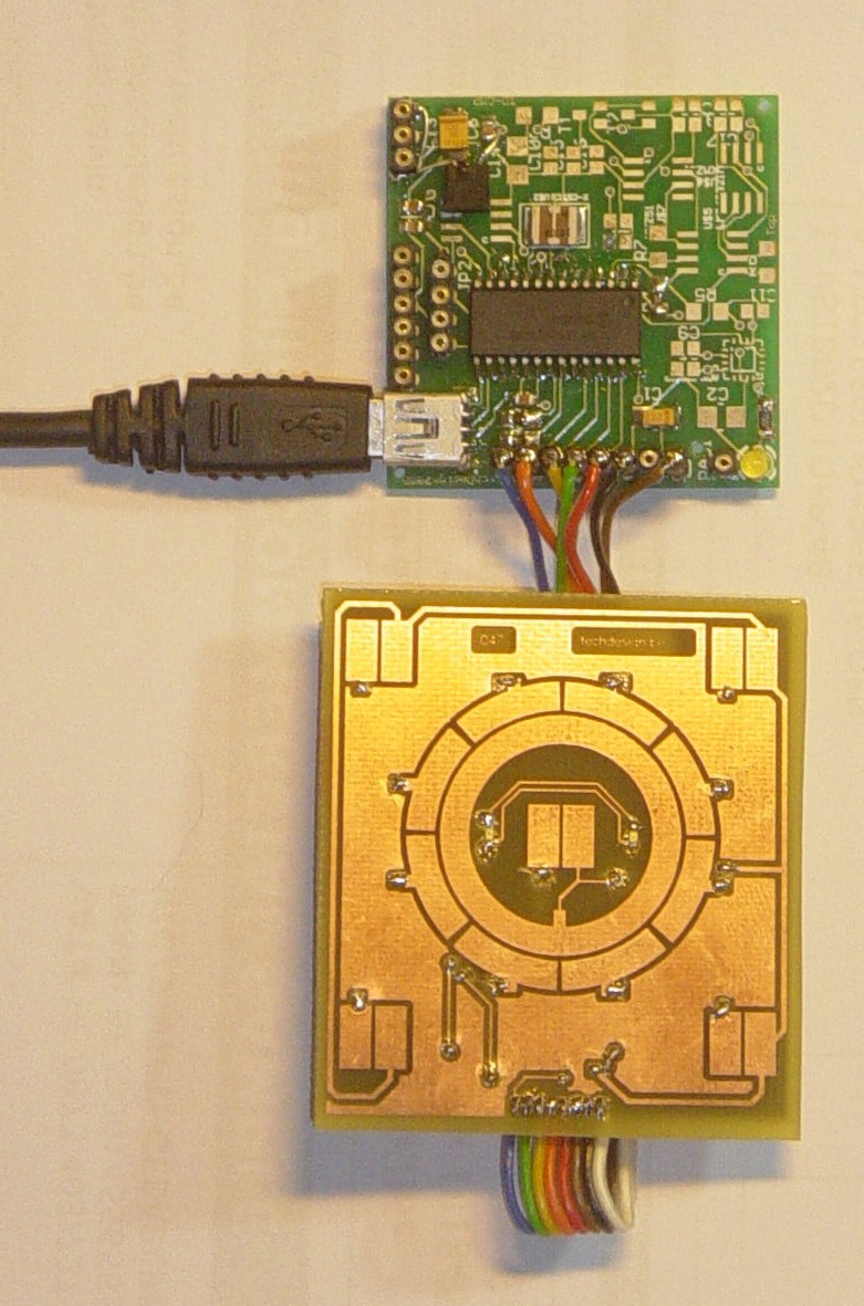
TD-USB-02 interface with touchpad sensor board and WinAmp interface.

This is an example USB project showing how to interface a touchpad sensor (the AD7142ACPZ) with a standard XP/Vista computer.

The TD-USB-02 board with a PIC18F2550 communicates with:

  • the PC: USB 2.0 through a mini-B connector.
  • the touchpad sensor board: SPI over 8-wire flatcable.
  • PC WinAmp application controls (start/stop, next/previous track, volume up/down).

Here are the technical specifications:

  • PC Win XP/Vista interface application with Visual C# 2008 Express: free download.
  • TD-USB-02 (green pcb on top) with PIC18F2550 USB HID setup.
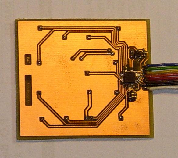
  • TouchPad sensor board (047) with AD7142ACPZ.
  • USB Bus powered, no external power supply needed.
  • Activation of central wheel scrollpad and three buttons from any distance between 2-5mm.
  • Works from within a plastic enclosure, thickness up to 3-4mm.
  • Two LEDs (right above and under the centre button) blink when a pad is activated.
  • Custom command activated by top right button (example: "c:\windows\explorer.exe" )
  • TD-USB-02 software is 100% upgradable with a simple RS232 bootloader.
  • RS232 interface for raw data readings.
  • PCB Dimensions: TD-USB-02 40 x 41 mm or 1"57 x 1"61

These assembled boards are available from our online shop.

Source code (CCS C and Visual C#) can be purchased separately.


Sensor example Source code (CCS C) , sensor board pcb layout and schematics (Eagle) available. 

Last update: May 3, 2009.

TD-USB-02 (green pcb on top)

TouchPad sensor board (047) (bottom pcb, top view)


PC Win XP/Vista interface application with Visual C# 2008 Express


TouchPad board: Schematic & PCB: (right click & "save as" to get full resolution)


TouchPad sensor board (047) (bottom view)

PCB layout (both layers, top and bottom)


TD-USB-02: Main Connections:


TD-USB-02 diagram

Header pinouts

Mouse sensor board (047)


SPI interface


TD-USB-02

 JP1 pins

1 +3V3 1.  +3V3
2 !INT 4. RB5
3 !CS 3. RB4
4 SCLK 2. RB3
5 SDI 5. RB6
6 SDO 8. RB7
7 GND 6. GND
8. nc   7. nc
 
TD-USB-01: JP2 RS232  
   
1 +5V
2 RX
3 GND
4 TX
 
Stages   11 10 9 8 7 6 5 4 3 2 1 0
CIN   2 12 11 10 9 8 7 6 5 4 3 13

Downloads: right-click & save as

 
  WARNING: may not be duplicated for any commercial use whatsoever without explicit consent from the author (c) Michel Bavin, TechDesign Electronics.


 TouchPad Board (047): Eagle PCB layout: 047_v005.brd  - Apr. 24, 2009.

 TouchPad Board (047): Eagle Schematics: 047_v005.sch  - Apr. 24, 2009.


 AD7142ACPZ: CCS c source code: touchpad_v01.c  - Apr. 24, 2009.

 TD-USB-02:Hex file: 047_v002.hex bootloading for the PIC18f2550  -  May 3, 2009.

 Windows interface application setup: 047_app_setup.zip  -  May 3, 2009. Written in Visual C# 2008 Express, compatible with Windows XP and Vista.


Get this page as PDF


Info & datasheet:

AD7142ACPZ
Generic_hid_cs
Microsoft Visual C# 2008 Express Edition


Tools:

Check out our development tools page.

The PIC code was made with the PCWH CCS compiler ($500,-); you can install Microchip's MPLAB IDE (click on the link and you can get it for free) with it to get things running smoothly.

Bootloading of the PIC18F2550 can be done with the excellent Tiny PIC bootloader, through RS232.

Eagle 4.11e was used for the schematic & PCB layout. 


Projects Home