|
 |
|
Dual programmable keypad code lock.
Open electrical doors with your secret code
only!
Here are the
technical specifications:
- Up to two keypads may be connected to drive both relay outputs.
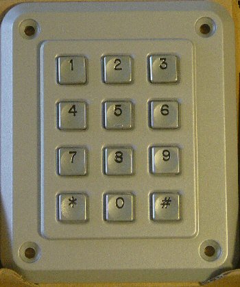
- Professional, outdoor or other keypads may be used.
- Relay outputs are configurable: output voltage +6 to +24VDC (from
power input) or simple switch emulation.
- The small LCD is optional, and can be omitted.
- Low power operation with internal switching power regulator and
microcontroller auto sleep mode: only 4 .. 8 mA at 12VDC
- The 4-digit secret codes can be changed by the user (previous code
needed.)
- Auto blocking after 5 wrong attempts.
- High-pitched piëzo sounds when striking a key.
- Keypad cable length up to 100m.
- This product will be available as
a KIT from our
online shop.
- Source code (CCS C) can be
purchased
separately.
PIC hex file ,
pcb layout and schematics (Eagle) available.
Last update: August 28, 2007. |
|
|
Interface: Schematic & PCB: (right click & "save
as" )
Interface:
Main Connections:
|
|
PCB diagram |
Header pinouts and connections |
|
 |
|
X1 |
Relay switched output 1 |
| |
|
|
1 |
+6 to 24VDC (JP1 position: right) or
switch_A (JP1 position: left) |
|
2 |
Ground (JP2 position: left) or
switch_B (JP2 position: right) |
| |
|
| |
|
X2 |
Relay switched output 2 |
| |
|
|
1 |
+6 to 24VDC (JP3 position: right) or
switch_C (JP3 position: left) |
|
2 |
Ground (JP4 position: left) or
switch_D (JP4 position: right) |
| |
|
| |
|
X3 |
Power input |
| |
|
|
1 |
+6 to +24VDC |
|
2 |
GROUND |
| |
|
| |
|
S1 RESET |
circuit reset key (same as power down) |
| |
|
S2 BLANK |
short press: relay output test long press (until beep)
resets the secret codes to: (do a reset first)
- "4711" and "8411" for relay output 1
- "4722" and "8422" for relay output 2
|
| |
|
U$1 LPH7779 |
Optional LCD connector (leave open when no LCD) |
| |
|
JP5 RS232 |
RS232 debug and bootloader (leave open for normal use) |
| |
|
JP6 RX433 |
Future wireless extension (leave open) |
|
JP7 ANT |
Future wireless extension (leave open) |
| |
|
ST1 |
Keypad 1 connector |
|
ST2 |
Keypad 2 connector |
| |
|
Instructions for use:
Secret code input: type the 4-digit code and press the # key to
activate relay output 1. Press the * key to activate relay output 2.
Changing the secret code: type the previous code and press # or * until the
piëzo sounds (after 5 sec.) Then type your new 4-digit code and press # or *
to finish.
Downloads:
right-click & save as
Info & datasheet:
|
|
|
|
|
|
|
Professional Storm keypads: 1K12T101-FEC |
|
|
|
|
|
|
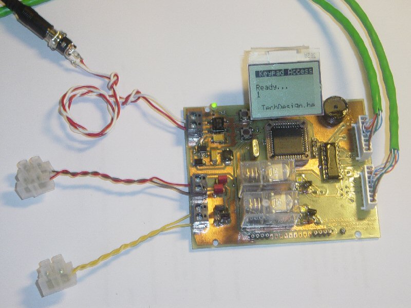
Screenshots:
|
Circuit overview |
|
 |
|
Tools:
Check out our development
tools
page.
The PIC code was made with the PCWH
CCS
compiler ($425,-); you can install Microchip's
MPLAB IDE (click on the link and you can get it for free) with it to get things
running smoothly.
Bootloading of the PIC18F452 can be done
with the excellent
Tiny PIC bootloader, through RS232
Eagle 4.11e
was used for the schematic & PCB layout.
Projects Home
