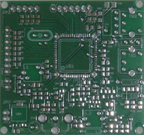
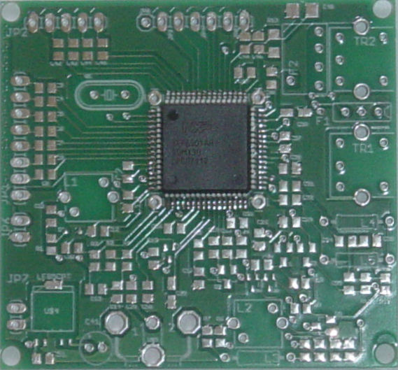
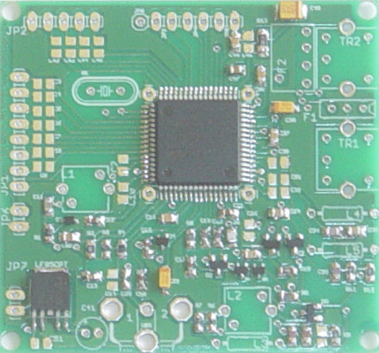
PCB, top view (picture)
These parts will fit on this side of the PCB:
- TEF6901AH/v2557 tuner chip
- 20,5 MhZ precision crystal.
- Connectors line in/out, power and I²C interfaces.
- coils, filters, transistors, resistors and capacitors.
PCB size = 61,4 x 57,3 mm
Double sided and 100% tested PCB with plated-through-hole connections.
All holes are drilled already.
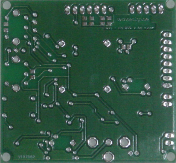
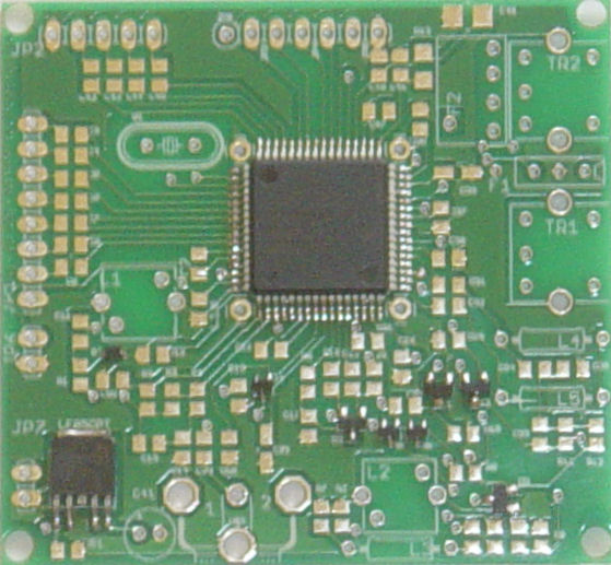
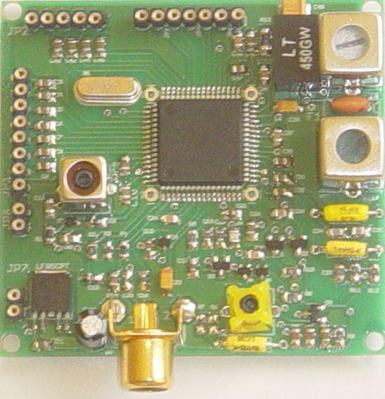
PCB, bottom view (picture)
As said above, only a couple of components here.
4 Resistors:
-
R14...R17: 10K SMD 0805 (103) or (1002) (on-part values)
2 Capacitors:
-
C36,C40: 5pF/5pF6 SMD 0603/0805
-
C1: not needed, leave unconnected.
Step 2: PCB top (drawing)
1 chip (integrated circuit)
- U$1: TEF6901/AH2557 (main chip)
Use a magnifying glass to do the soldering.
First pre-solder pin1 of the main chip by adding a bit of solder to this pin. Then place the chip onto the PCB and make sure pin 1 is well placed.
The white dot on the drawing point to pin 1 of the chip. On the PCB, there is a small " ° " etched near pin 1.
Main chip has been soldered.
Check for shorts between the pins and see if each pin is well connected to its pad. Use a conductivity meter (most multimeters have those) to look into this.
In case you made a short (with the use of too much solder for example) Stay cool (!) and then desolder with desoldering braid like 3S-WICK or Chem-XIK.
Now we'll have to solder some smaller SMDs.
A good trick is to pre-solder one pcb pad by applying a bit of solder to it. Then place the SMD with the help of a wooden toothpick, whilst soldering the SMD to the pad you've just presoldered. Then solder the remaining pin(s.)
6 Diodes:
-
D1: BB208-03 (A2) (on-part values)
-
D2: BB207 (P13)
-
D3: BAV99 (A7)
-
D4: BAP64-04W (4W)
-
U$2,3: BAP70-04W (1N)
2 Transistors:
-
T1: BF862 (2AW)
-
T2: BC848 (1GW)
1 Chip:
U$4: LF85CPT
Step 5: PCB top (drawing)
13 resistors and 28 capacitors
13 Resistors: SMD 0805
-
R1: 4K7 (472) or (4701) (on-part values)
-
R2: 10K (103) or (1002)
-
R3: 2K2 (222) or (2201)
-
R4: 1K2 (122) or (1201)
-
R5: 22K (223) or (2202)
-
R6: 47K (473) or (4702)
-
R7: 470K (474) or (4703)
-
R8: 82R (820)
-
R9, R11: 560R (561)
-
R10: 1M5 (155) or (1504)
-
R12: 47R (47R0) or (470)
-
R13: 47R SMD 1206 (47R0) or (470)
28 Capacitors: SMD 0603/0805
C11: 270pF
C12, C15, C17, C21, C50: 1nF
C13: 3n9
C16, C37, C38, C48: 22n
C18, C19: 6p8
C20: 8p2
C22, C39, 1µF polarized tantalum (105)
C23: 100p
C24, C27: 10n
C25: 220p
C29, C35: 220n
C33: 27p
C34: 47p
C41: 2,2µF polarized electrolytic
C47: 1µF
C49: 33/47µF polarized tantalum (336 or 476)
C52: 3n3
IMPORTANT: tantalum capacitors: +pins are marked by coloured band