FM RDS Tuner Module

Get this page as PDF

TechDesign Electronics


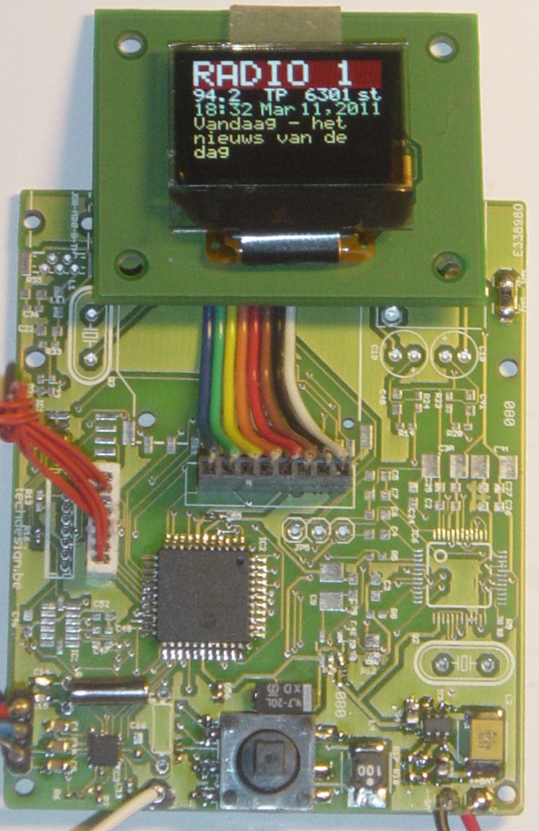
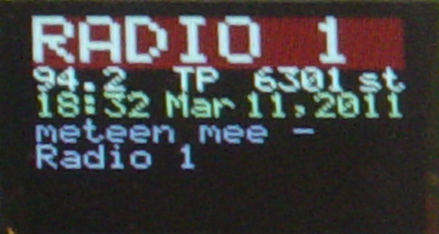
KIT1 with OLED module running.


FM RDS Tuner Module for mobile applications.


  • Stereo FM band receiver with RDS decoding for mobile applications.
  • Continuous full RDS data output through RS232: RDS PS, PI, TA/TP/TMC, CT, TMC.
  • Full Radio Text supported: 2x64 characters.
  • Raw TMC data output.
  • Low power operation with two AA (HR6) 1V2 Ni-Mh batteries or power supply.
  • Power input range is +2.4V ... +3.0V, 50..60mA without OLED and 80..90mA with OLED.
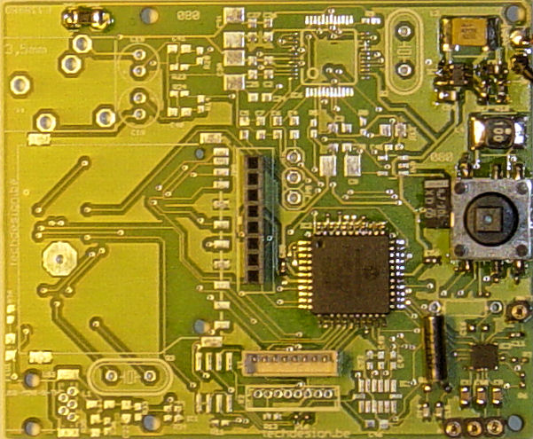
  • Runs on a PIC18F46K20 at 16 MhZ.
  • Full user control (volume, tune, save preset) with a 5-way micro joystick.
  • Module works as stand-alone without OLED as well.
  • Optional OLED Module 1 with RGB OLED 96x64 pixels shows PS (station name), frequency, TA/TP/TMC, PI, mono/stereo, RT (2 alternating lines of radio text)
  • Serial interface control so the module may be used as a stand-alone module.
  • Analog line stereo output.
  • Antenna connection, suggest use of a 30cm -> 2m wire.


 Schematic & pcb (Eagle 4.11e), hex file available. Module Software Updated on March 12, 2011.


Circuit explanation / Getting started:


PIC18F46k20   The 18F46k20 offers high speed and low power operation. Well suited for a portable application such as this one.
Si4731/4735   Small tuner chip, includes a RDS demodulator.
OLED   OLED Module 1 with 96x64 pixels RGB OLED, Size: 0.95"

Needs a +14V Vdd, this is generated by a TPS61080.

Controls   With the micro joystick, there are several user controls available. Two for volume (up & down) , tune (left & right) and save preset (short enter.) Zone can be selected on boot:

Zone 1 (USA): FM 87,50 -> 108.0 MhZ (75µS setting) To select this zone: left joystick and release on bootup or restart.

Zone 2 (EURO): FM 87,50 -> 108.0 MhZ (50µS setting): Up joystick.

Zone 3 (JAPAN):  FM 76,0 -> 108.0 MhZ (50µS setting): Right joystick.

Serial interface:  tune up and down (tup & tdn) , set frequency (setxxx.x), save preset (sav), get frequency (get), show basic rds info (rds ), reset module (res)

Preset and zone are stored and reloaded on reboot.

Power   The MCP1640 DC-DC step-up converter makes it possible to power the whole circuit from only one AA battery. We have chosen two AA batteries for enhanced stability and endurance. Power input range is +2.4V ... +3.0V Do not exceed this!
PCB:   We used as much SMD-parts as possible. The PCB from our shop is a double sided and 100% connection tested PCB with plated-through-hole connections. All holes are drilled already. PCB size = 66,50 x 54.90 mm


Schematics: (eagle-files and library can be downloaded below.)

Full resolution image: schematic and pcb (GIF format) Right-click and save as, then open in an image viewer (sch is too large for some browsers.)

Bill of Materials (Parts List)

Important note: The following sections from the schematic are not needed in this particular setup, and are left out on assembly: EE_PROG, USB+SD, MP3, ACCELERATOR.


Main connections:


JOYSTICK CONTROLS

PIC18F46K20   OLED PIC18F46K20   X1 - ICSP - RS232 PIC18F46K20  
                   
   Joystick Up: Volume Up  RA1,pin20    1 - !RES  RC0, pin32    1 - MCLR  MCLR, pin18  
   Down: Volume Down  RD7,pin5    2 - D/!C  RC1, pin35    2 - PGD  RB7, pin17  
   Right: Tune up  RA0,pin19    3 - !CS  RC2, pin36    3 - GND    
   Left: Tune down  RD6,pin4    4 - D0  RB6, pin16    4 - PGC  RB6, pin16  
   Enter: save current frequency as preset  RA2,pin21    5 -VDD +3v3      5 -+3v3    
         6 - D1  RB7, pin17    6 - NC    
         7 - GND      7 - PICRX  RX, pin1  
         8 - VCC +14v      8 - PICTX  TX, pin44  


Downloads: right-click & "save as"

 
  WARNING: may not be duplicated for any commercial use whatsoever without explicit consent from the author (c) Michel Bavin, TechDesign Electronics.
 

 Schematic: 086_v025.sch and library (Eagle 4.11e), Dec. 23, 2010.

 PCB: 086_v025.brd (Eagle 4.11e) Jan 31, 2011.
 PIC Hex files: 086_v003.hex (Eagle 4.11e) Mar. 12, 2011.


 PIC Source Code (ccs pcwh): not released, but you can buy a license on this Products page.

Get this page as PDF


Info & datasheet:

KIT1: terminal screen screenshot

 
Si4731/4735 tuner chip.
 
OLED Module 1 with 96x64 pixels RGB OLED, Size: 0.95"


RS232  connector pinout:

Look here to build the (very simple) terminal (RS232 level converter) hardware. Or use a USB to serial converter.

Download the Tiny PIC bootloader from the same site. We are using version 1.8 (Don't use version 1.91)

Or use a direct connection to/from another PIC or µC. Then simply cross the RX/TX lines.


RS232 controls and  Command set


  • Player control via RS232 terminal. (X1: RS232 Level converter/ serial com port @115200 bpS with "type communication") Or use a direct connection to/from another PIC or µC. Available commands (in green:)


  • Tune up: tup<ENTER>
  • Tune down: tdn<ENTER>
  • Save preset: sav<ENTER>
  • Get current frequency: get<ENTER>
  • Show basic RDS info: rds<ENTER>
  • Goto frequency: setxxx.x<ENTER>   examples: goto 100.9 MhZ: set100.9<ENTER> or goto 89.5 MhZ: set089.5<ENTER>
  • Reset module: res<ENTER>


Note: the serial controls may be used along with the joystick.


Screenshots:

PCB diagram


KIT1, Assembled PCB image, without OLED (real size = 66,50 x 54.90 mm )


OLED detail:


Tools:

Check out our development tools page.

The PIC code was made with the PCWH CCS compiler ($500,-); you can install Microchip's MPLAB IDE (click on the link and you can get it for free) with it to get things running smoothly.

Programming of the PIC was done with a GTP-USB+ hardware programmer along with the WinPic800 software.

Eagle 4.11e was used for the schematic & PCB layout. 


Projects Home