|
Compass, Tilt/Roll
and Temperature sensor applications with the TD-CMP modules. |
Projects
Home |
|
 |
|
This page will show you how to use the TD-CMP modules in a way
which fits you most.
Here are the technical specifications of the modules:
- Compass: Resolution: 1° - Accuracy: 3°
- Tilt/Roll: (TD-CMP02 and TD-CMP03 only) Resolution: 2° - Accuracy: 5°
- Temperature: (TD-CMP03 only) Resolution= 1°C/F - Accuracy =1°
-
New: Sampling rate: 12,5 to 25 samples/second.
- Easy Tilt/Roll calibration.(TD-CMP02 and TD-CMP03 only)
- Interfaces: I²C, RS232 and mini-USB (as a HID device: PID=0461, VID= 1023)
- Powered by USB bus or an external 5V.
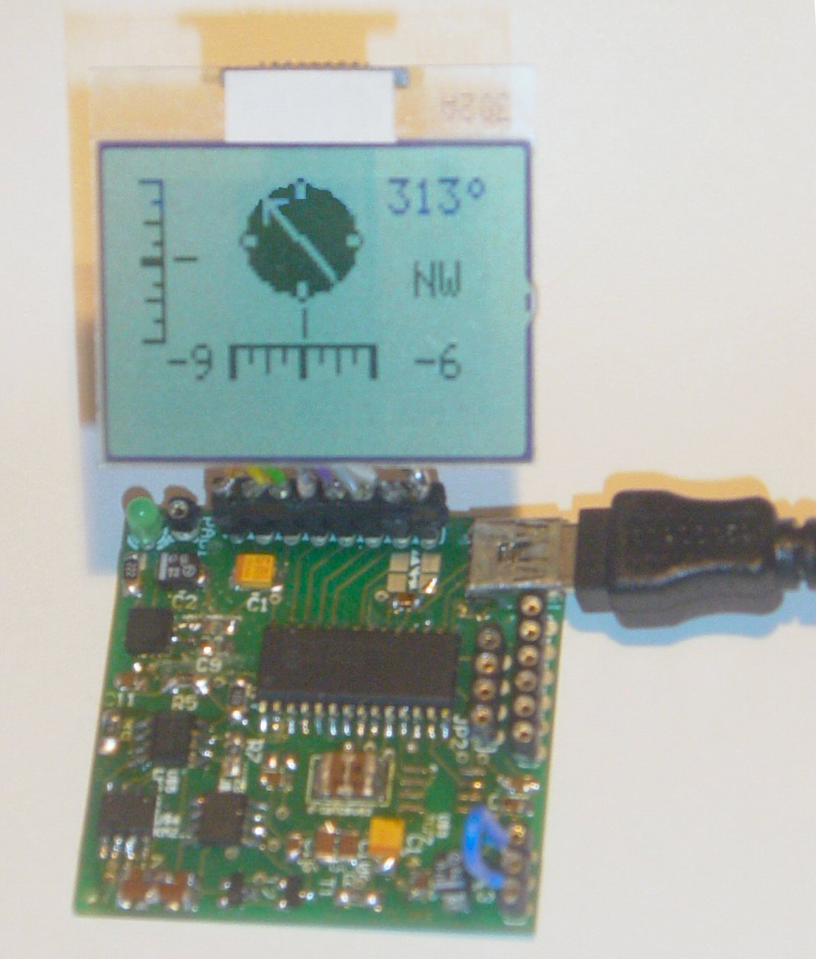
- Direct LCD readout possible. LCD contrast by user.
- Low power LED lights when facing North (angle
within 11,25° both left and right from North.)
- USB Windows application (written in C#) available for
free download.)
Compatible with WinXp/Vista.
- Source code (CCS C and C# .NET) and schematics (Eagle) can be
purchased separately.
- Module software is 100% upgradable with a simple bootloader.
- PCB Dimensions: 40 x 41 mm or 1"57 x 1"61, weight: 10 grams.
These assembled modules are available from our
online shop.
You
may also purchase the
bare pcb, a
KIT DIY* version and the
source code. KIT step-by-step construction guide.
New: compass
calibration.
Schematics and pcb diagrams available for download.
Last update: November 26, 2009.
DIY* = Do It Yourself
|
Screenshots:
|
C# Windows Example Program |
|
 |
Schematics: (click for full resolution image)
Main Connections:
|
Module header diagram |
|
Header pinouts |
 |
|
| |
JP2 pins |
RS232 |
|
JP3 pins |
I²C / TEMP
SENSOR |
|
JP4 pins |
POWER
SOURCE |
| |
|
|
|
|
|
|
|
|
| |
1 |
+5V |
|
1 |
+5V |
|
1 |
EXT (from
JP3) |
| |
2 |
RX |
|
2 |
SCL/SPEED1 |
|
2 |
COMMON |
| |
3 |
GND |
|
3 |
SDA |
|
3 |
USB |
| |
4 |
TX |
|
4 |
GND / TEMP
SENSOR -/SPEED2 |
|
|
|
| |
|
|
|
5 |
ADJUST |
|
|
|
| |
|
|
|
6 |
TEMP SENSOR + |
|
|
|
| |
|
|
|
|
|
|
|
|
| |
*
Note: pin 1 is marked by red in the diagram |
|
Power Source: JP4: Connect pin 2 to pin 3 to power
the module directly from USB. Connect pin 1 to pin 2 when powered externally via JP3, pin 1.
New:
Increase sampling
speed from 12,5/second to 25/second: connect SPEED1 to SPEED2 (JP3,
pin4 to JP3, pin2.)
LCD contrast Adjust: Connect pin 5, JP3 to +5V before powering up.
Release when the desired the contrast is reached.
Tilt/Roll Calibration: (TD-CMP02 and TD-CMP03 only):
- First place the module on a
completely flat surface, power up.
- Then shortly apply +5V (pin 1, JP2) to ADJUST (pin 5, JP3)
Release after 1 second.
- Check readings when applying tilt/roll to
the module. Repeat the
calibration procedure if necessary. Done.
Compass Calibration:
(do not touch the PCB or chips whilst calibrating.)
- First place the module on a
completely flat surface, power up, head to North (position as shown in diagram
and picture above), then turn the module slowly 360° (make 2-3 full clockwise
and/or counter-clockwise spins.)
- Now apply +5V (pin 1, JP2) to ADJUST (pin 5, JP3) Wait
for 8-10 seconds; the LED will flash 3 times. Release the ADJUST pin from +5V. Power off and on.
- Check compass readings when heading the
module to N, S, E, W. Repeat the calibration procedure if necessary. Done.
Module RESET: apply GND to MCLR pin.
Temperature sensor: (TD-CMP03 only): The external LM335Z sensor
connects to JP3 pin 4 and 6. No temperature will be displayed when the sensor
is removed.
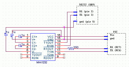
RS232 interface:
JP2 provides the interface to connect to your COM
port and hyper terminal. Communications @ 115200 bpS, 8N1.
Use a level converter like the MAX3232 between the TD-CMP module and the pc
serial port. See
this example.
Also used for bootloading (module software update.)
Check under the download section below for the latest version. Bootloading of
the HEX-file can
be done with
Tiny Bootloader 1.91
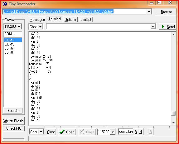
RS232 terminal screen @115200 bps
I²C interface: JP3 allows us to connect to another µC. The module is
the slave device on address 0xa0. It can be read via a simple EXT_EEPROM
command. Download
this I²C CCS C example to see how to connect I²C with a 18F452. Don't
forget to change the POWER SOURCE (JP4) and connect pin 1 to pin 2.
Internal 8 bit registers are:
- i2c_buffer[7]= t_hi; //
temperature high byte (unsigned int8)
i2c_buffer[6]= t_lo;
// " " " "
low byte
- i2c_buffer[5]= adxl_y;
// roll (signed int8)
i2c_buffer[4]= adxl_x;
// tilt " " " "
i2c_buffer[3]= cmp_UMSB;
i2c_buffer[2]= cmp_LMSB;
i2c_buffer[1]= cmp_ULSB; //
compass 0..359
i2c_buffer[0]= cmp_LLSB; //
" " " "
Reading the module (ccs c code):
- #include
<2401.c>
// for I²C EXT.EEPROM emulation used
by slave i²c TD-CMP modules
- ...
- int8 cmp_LLSB,cmp_ULSB;
- int16 compass_degrees;
- signed int8 adxl_x,tilt_degrees;
- signed int8 adxl_y,roll_degrees;
- ...
- init_ext_eeprom();
// init TD-CMP module as slave I²C ext.EEPROM
- ...
- cmp_LLSB = READ_EXT_EEPROM(0x00);
// read TD-CMP register 0
(cmp_LLSB)
- cmp_ULSB = READ_EXT_EEPROM(0x01);
// read TD-CMP register 1
(cmp_ULSB)
- adxl_x = READ_EXT_EEPROM(0x04);
// read TD-CMP register 4 (adxl_x) Tilt
- adxl_y = READ_EXT_EEPROM(0x05);
// read TD-CMP register 5 (adxl_y) Roll
- ...
- compass_degrees= ((int16)cmp_ULSB<<8)+cmp_LLSB;
// here's the data we needed
- tilt_degrees= adxl_x;
- roll_degrees= adxl_y;
USB interface: is HID (Human Interface Device)
on PID=0461, VID= 1023 Each packet is 8 bits long (4 bytes address and
4 bytes data.)
- Address 0x01000004: cmp_UMSB, cmp_LMSB, cmp_ULSB, cmp_LLSB (compass)
- Address 0x01000003: t_hi, t_lo (temperature), adxl_y (roll), adxl_x (tilt) signed int8
Low power LED: Will light up shortly when USB is connected and
enumerated. Also the LED will blink several times,
according to the capital direction it is facing:
- North: 1x
- East: 2x
- South: 3x
- West: 4x
Downloads:
right-click & save as
Info & datasheet:
Tools:
Check out our development
tools
page.
The PIC code was made with the PCWH
CCS
compiler ($425,-); you can install Microchip's
MPLAB IDE (click on the link and you can get it for free) with it to get things
running smoothly.
Bootloading of the modules is done
with the excellent
Tiny PIC bootloader, through RS232 (JP2).
Eagle 4.11e
was used for the schematic & PCB layout.
Projects Home