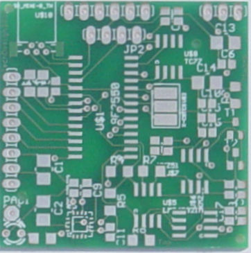
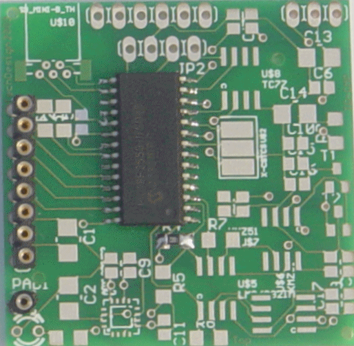
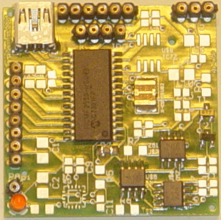
PCB, top view (picture)
These parts will fit on this side of the PCB:
- PIC USB microcontroller 18F2550-I/SO
- 20 MhZ crystal resonator.
- Connectors to the LCD (ICSP), RS232 and I²C interfaces.
- Sensors, chips, transistors, resistors and capacitors.
size = 41,2 x 41,2mm
Double sided and 100% tested PCB with plated-through-hole connections.
All holes are drilled already.
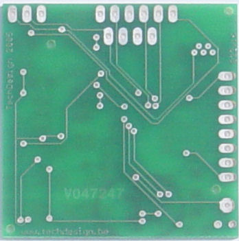
PCB, bottom view (picture)
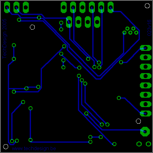
Step 2: PCB top (drawing)
IC1 (PIC18F2550) + U$11 (ICSP) + PAD1 + R4
- Chip IC1: PIC18F2550-I/SO
- Connector U$11 (ICSP and LCD connector, 8-pin SIL)
- PAD1: !MCLR
- Resistor R4: 10K SMD (103) or (1002) (on-part values)
This is the PCB you get when you buy TD-CMP KIT1
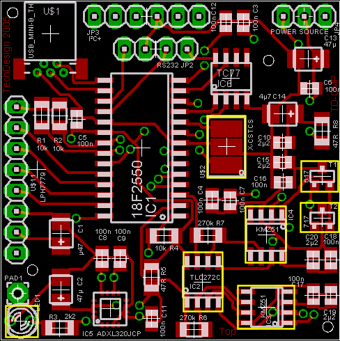
ICs:
-
IC2: TLC272C opamp
-
IC3: KMZ51 sensor
-
IC4: KMZ51 sensor
Transistors:
-
T1: FMMT617
-
T2: FMMT717
U$2: Crystal resonator 20MhZ (presolder the middle pcb-middle pin first)
LED1: 3mm low power LED (2...3 mA) Kathode (- pin) is closest to the leftt-hand pcd corner.
- JP2: RS232 (4-pins SIL)
- JP3: I²C+ (6-pins SIL)
- JP4: POWER SOURCE (3-pins SIL)
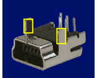
- U$1 (USB mini-B connector): first remove the 2 rectangular green layers from the pcb at the connector rear edges. Scratching a bit with a sharp cutter will do. Now cut the two middle grounding connector pins away with a sharp cutter: see picture below:
We're almost through.
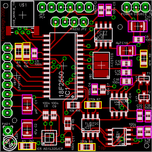
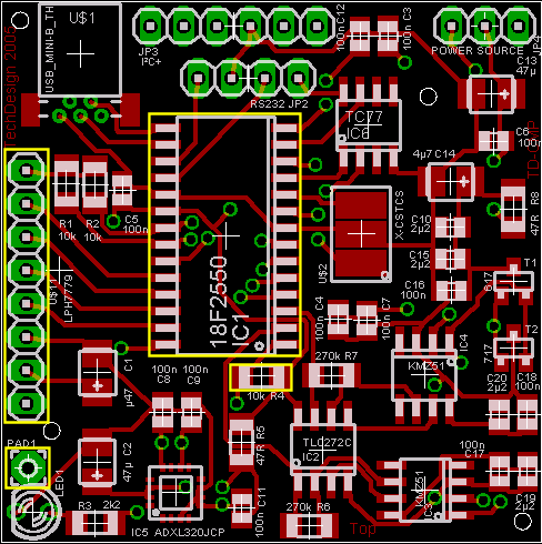
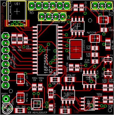
Step 5: PCB top (drawing)
5 resistors and 16 capacitors
Resistors:
-
R1, R2: 10K (103) or (1002) (on-part values)
-
R3: 2K2 (222) or (2201)
-
R6, R7: 270K (274) or (2703)
-
R8: 47R (47R0) or (470)
Capacitors:
IMPORTANT: tantalum capacitors +pin is marked by coloured band
-
C1: 0,47...1µF polarized SMT or tantalum case B
-
C2: 33...47µF tantalum case B or C
-
C3, C4, C5, C6, C12, C16, C17, C18: 100nF ceramic
-
C13: 33...47µF tantalum case B or C
-
C14: 4,7µF/25V case B or C
-
C10, C15, C19, C20: 2,2µF ceramic
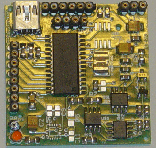
PCB, top, after step 5 (picture)
That's it! You now have completed the TD-CMP KIT1 compass.
Have lots of fun building it!
Cleaning of the pcb to remove flux may be done with a PCC (printed circuits cleaner,)
Have a look at the TD-CMP project page to get it working. You'll need to connect JP4: POWER SOURCE (3-pins SIL) according to the power source:
- USB powered: Connect pin 2 to pin 3 (middle and corner right pins connected.)
- External power +5V via JP3: Connect pin 2 to pin 1 (middle and left pins connected.)
You will also need to do the tilt-roll and compass calibrations, see the TD-CMP project page for details.