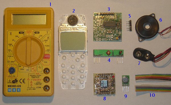
WMM KIT 1 contents (picture)
- DMM (Digital MultiMeter) M830D
- Nokia 3310 LCD
- RX circuit
- RX-433 module
- SIL contacts
- Piezo buzzer
- 9V battery clip
- TX circuit
- TX-433 module
- Flatcable
Blue= TX (DMM, TX circuit and module)
Black= RX (RX circuit and module, LCD, Buzzer)
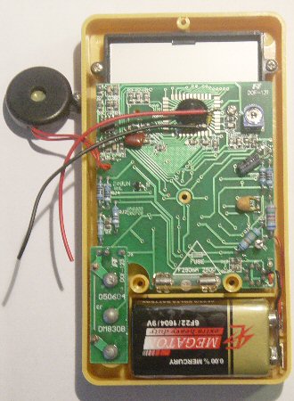
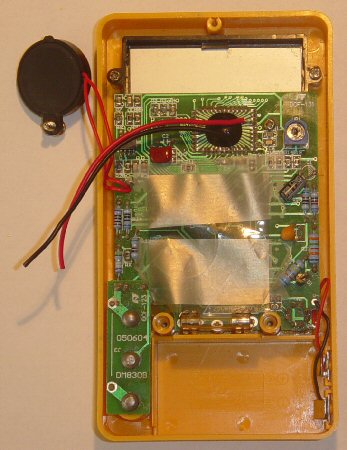
Step 1: DMM (picture)
Let's start with the transmitter (TX).
First of all, be sure to disconnect the DMM from any input (remove the input plugs.)
-
Open the DMM (3 screws.)
-
There are two loose wires (a red and a black one) which are connected between two zener diodes (yellow or reddish) onto the pcb. We'll connect these in step 3.
-
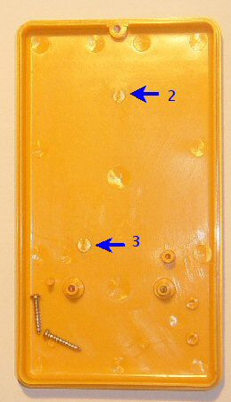
Unscrew the buzzer
-
Remove the first plastic placeholder (with a strong and sharp cutter)
-
Remove the second one.
Remove the 9V battery should there be one included. Normally it's already removed prior to shipment.
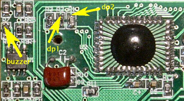
- Buzzer
- dp1
- dp2
LCD and DMM chip details (drawings)
DMM chip details 2
As you see, each LCD segment is available for use. For example: DMM chip, pin 16 is "D3" This corresponds to the d segment of digit 3.
IMPORTANT: the DMM chip COM pin remains unconnected.
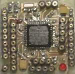
TX circuit overview (picture and drawings)
Connection details
-
JP1 connects to the TX-434 module
-
JP2 is the RS232 interface and is only needed for bootloading and debugging.
-
JP3, JP5, JP6, JP7 and JP8 will connect directly to the DMM chip (with flatcable.)
Have the above DMM chip and TX circuit drawings printed for reference.
- Isolate the DMM PCB with some plastic foil.
- Connect the red wire (DMM chip +V) to JP3, +V
- Connect the black wire to JP3, GND
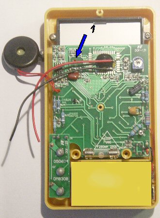
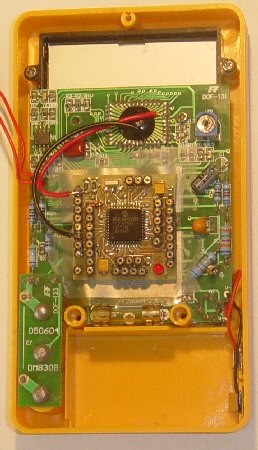
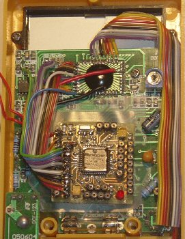
Step 4: DMM (pictures)
JP3 (continued) wiring
- Prepare a 5-wire flatcable (strip them at one end and presolder them)
- Solder the DMM chip contacts G2, C3, A3, G3 and BP to the flatcable.
- Bend the flatcable to save space.
- Cut it right over JP3.
- Connect the flatcable to JP3.
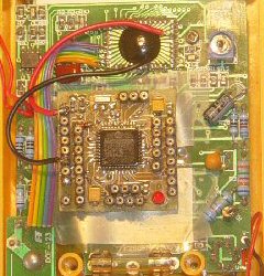
-
Start with the Buzzer, Lobat, dp1 and dp2 contacts. Connect the DMM contacts to the 8-wire flatcable.
-
Be sure to leave the Buzzer-screwhole (see step 1) a bit of free space.
-
Continue with the POL, AB4, E3 and F3 contacts.
-
Connect the flatcable to JP6.
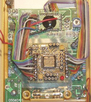
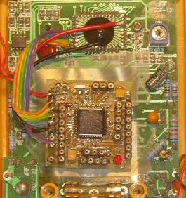
- Connect the 8 DMM contacts to the 8-wire flatcable.
- Connect the flatcable to JP5.
- Connect the B3, D3, E2 and F2 DMM contacts to 4-wire flatcable.
- Connect the D1, C1 and B1 DMM contacts to 3-wire flatcable.
- Connect the flatcables to JP7 and JP8.
OK! All LCD connections are now done.
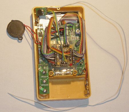
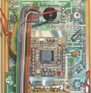
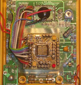
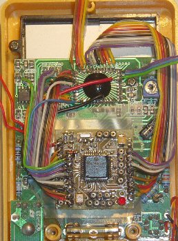
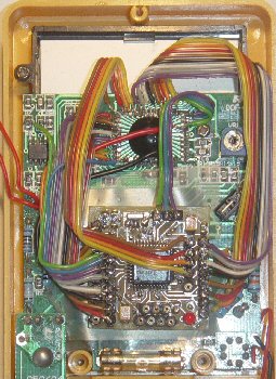
Step 8: TX-434 module and DMM (pictures)
JP1 wiring
- Shorten the TX-434 module contacts.
- Connect the 3 leftmost contacts to some flatcable. These are (from left to right) GND, TX_IN and +V
- Connect the flatcable to JP1.
- Connect a 30-35cm wire to the modules rightmost pin. This is the ANTenna.
The TX part is now done. Replace the DMM buzzer and screw it in again. Put the battery back in and close the DMM again (back cover with 3 screws.)