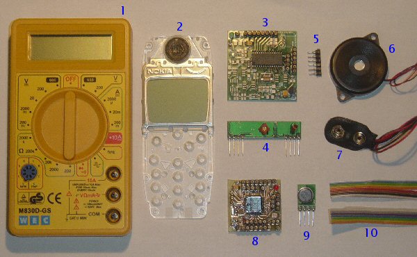
WMM KIT 1 contents (picture)
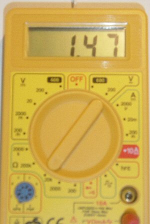
- DMM (Digital MultiMeter) M830D
- Nokia 3310 LCD
- RX circuit
- RX-433 module
- SIL contacts
- Piezo buzzer
- 9V battery clip
- TX circuit
- TX-433 module
- Flatcable
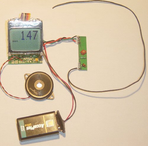
Blue= TX (DMM, TX circuit and module)
Black= RX (RX circuit and module, LCD, Buzzer)
-
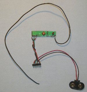
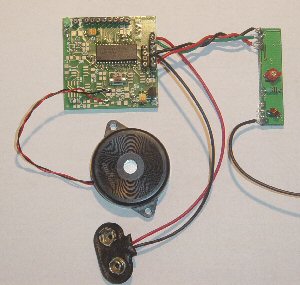
This left picture shows what we have at this stage.
-
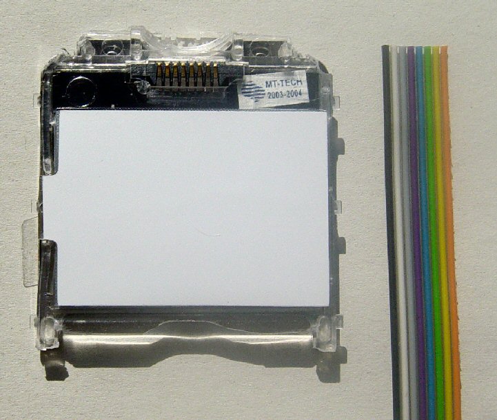
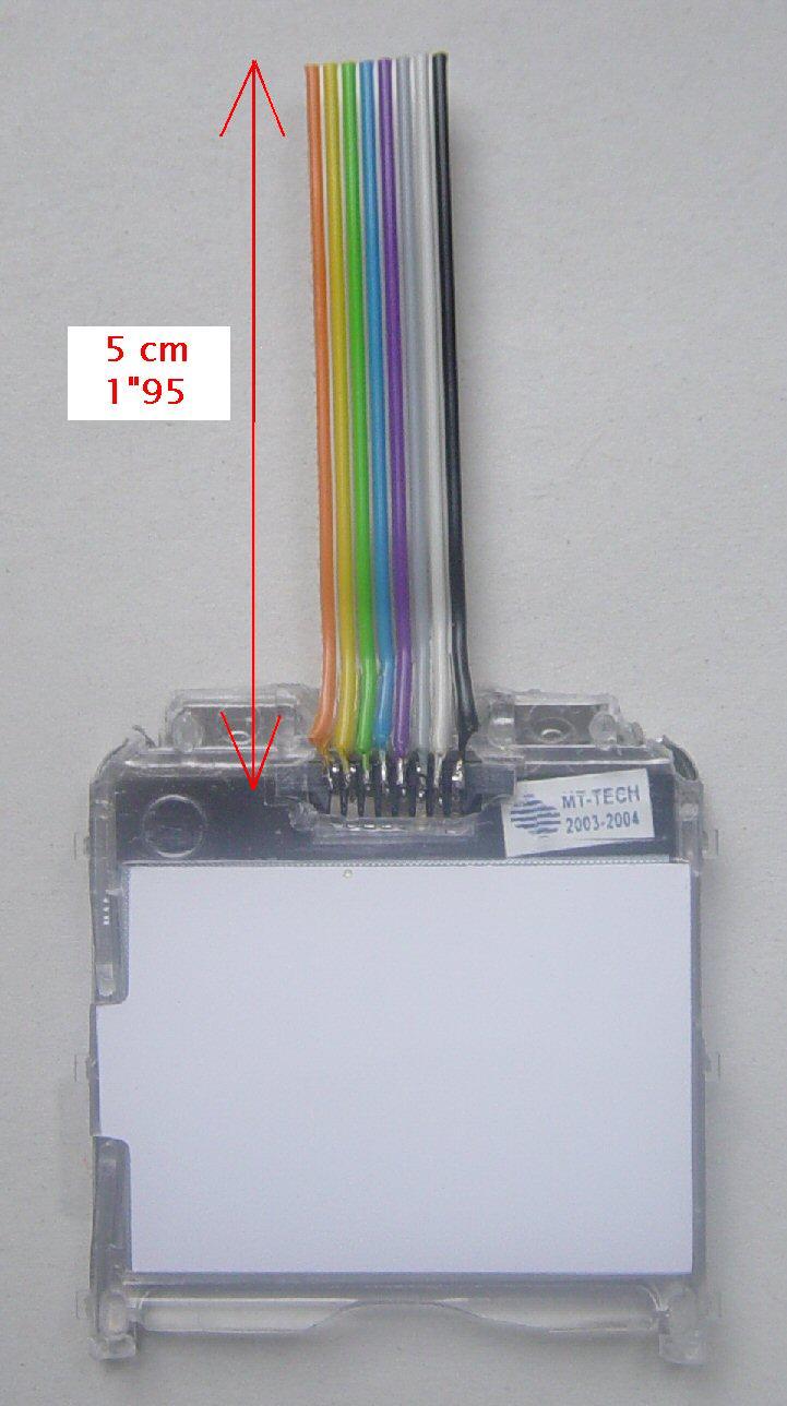
Now get the flatcable (8-wired) ready.
-
Strip the flatcable, twist and pre-solder the wires and cut the ends.
-
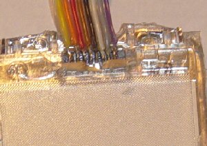
Pre-solder the LCD-contacts (only topmost side.)
-
Solder the flatcable onto the LCD-contacts.
-
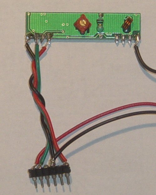
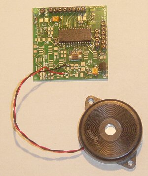
Now you should have something like on the right picture.
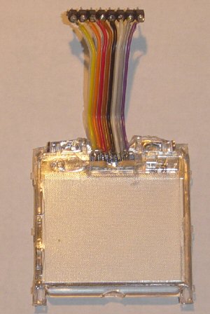
Finish by soldering the other end of the flatcable to a SIL-connector.
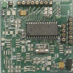
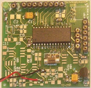
RX circuit (picture and drawing)
Overview and pinout.
- JP1: LCD
- JP2: RS 232 (only for bootloading and debugging)
- JP3: RX-434 module, power:
| 1 | +9V input from battery |
| 2 | input from RX-433 module |
| 3 | NC (no connect.) |
| 4 | GND (to battery and RX-433) |
| 5 | LCD contrast adjust input |
| 6 | +5V output (to RX-433) |
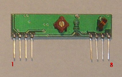
RX-434 module
Overview and pinout.
| 1 | gnd |
| 2 | digital output |
| 3 | linear output |
| 4 | Vcc |
| 5 | Vcc |
| 6 | gnd |
| 7 | gnd |
| 8 | antenna (30-35cm) |
- Shorten the RX-434 modules pins and presolder them.
- Connect the 9V battery clip to the 6-pin SIL-contact.
- Connect the RX-434 module to the 6-pin SIL-contact.
- Solder a 30-35 cm antenna (normal wire) to pin 8 of the RX-434 module.
Step 12: Buzzer.
connection to RX circuit
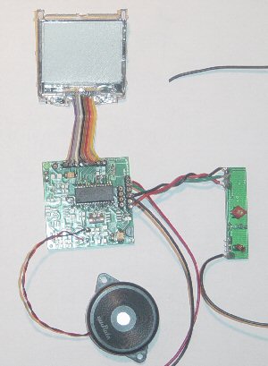
-
Connect the 6-pin SIL to JP3.
-
Connect the LCD to JP1.
-
Plug in a 9V battery.
-
Adjust the LCD contrast by holding JP3, pin5 high during boot. Release when the desired LCD contrast is reached.
-
Turn on the DMM and see if you can receive a signal.
-
Enhance the RX-434 module signal reception by adjusting the red coil (in the middle of the PCB.)
Done!