|
 |
|
This project supports both RDS (Europe) and RBDS (USA) Tuner FM band 88..108 MhZ
(Europe and USA.)
You can choose between a 4x20 character LCD
or a smaller graphical LCD to display data.
A simple RS232 interface can also be used.
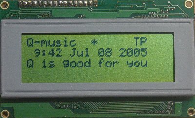
A 4x20 character LCD module will display these:
- 1st row: Station name (PS), Quality, Program Identification
(PI), Traffic Program (TP)
and Announcement (TA)
- 2nd row: Time and Date (CT)
- 3rd row: Radio Text Line A (RT) 64 scrolling characters.
- 4th row: Radio Text Line A (RT) 64 scrolling characters.
All major parts are available from our
online shop.
Schematic & pcb (Eagle 4.11e),
hex file available.
Last updated on December 12, 2007. |
Circuit explanation
The schematic consists of two major subcircuits:
If you want to build this decoder into an existing tuner,
then you won't need to rebuild the tuner part of the circuit. All you need to do
then is to look for an MPX-signal in your existing tuner. This is usually
found before the stereo decoder chip. This MPX signal must then be fed to the
TDA7330 through a 47nF capacitor.
The circuit needs a couple of seconds of valid RDS/RBDS
data before driving the LCD.
Quality indicator: a stable arrow (first row on the
LCD) means the reception is good. Blinking arrows however indicate no valid
RDS/RBDS data is being processed (signal too weak or station transmits no RDS/RBDS
data.)
Digital tuning and volume control: the joystick
gives us to have full control over the circuit. Last values are stored and
reloaded on boot.
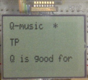
You'll have to choose a 4x20 character LCD or a smaller
graphical LCD to display data. The smaller graphical LCD is best suited
for portable applications, whereas the larger 4x20 character LCD is best for
fixed receivers (f.e. in your car). Which display is driven can be chosen when
booting: joystick-left for the 4x20 and joystick-right
for the smaller LCD.
The RS232 interface also shows all decoded data properly
(see the screenshot below.)
|
RDS decoder: |
|
TDA7330 |
|
RDS/RBDS decoder chip.
Needs an MPX input in order to decode RDS/RBDS data. |
|
PIC18F452-I/L PLCC |
|
This Microchip PIC
microcontroller does most of the work: it looks for valid RDS data, then drives the LCD. |
|
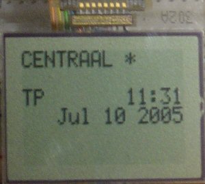
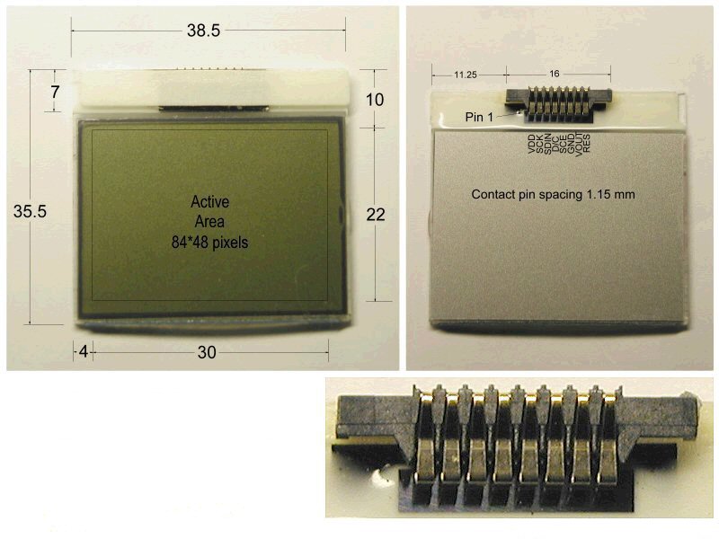
Graphical LCD |
|
Nice little graphical LCD
LPH7779 (Nokia 3310 LCD)
Low power and best for portable use. Contrast adjustment by pressing
volume up or volume down whilst booting. |
|
LCD Module 4x20 |
|
Standard 4-lines x 20-characters
LCD
module. Best choice for fixed receivers. |
|
FM stereo tuner: |
|
TDA7021T |
|
FM Tuner with MPX output.
Some handmade coils are needed (more info about how to make these below.) |
|
TDA7040T |
|
Philips PLL Stereo decoder.
Needs only a couple of external components. |
|
TDA7050T |
|
Low power stereo headphone
amplifier. Small package and low power but still good quality. |
|
Controls |
|
With
the
micro joystick, there are 5 user controls available. Two for volume (up &
down) , tuning (left & right) , save
preset (push).
|
|
MCP41010-I/SN |
|
256-step 10k SPI digital
potentiometer for tuning. A multiturn potentiometer is a (more
expensive) alternative. |
|
MCP42010-I/P |
|
Dual 256-step 10k SPI digital
potentiometer for volume control. Replaces a double stereo
potentiometer. |
All coils use 0,5mm diameter coated copper wire and
measure 5mm in diameter.
-
L1, 78nH: 8 windings, little spacing.
-
L2, 56nH: 5 windings, more spacing.
Main connections:
|
|
| SPI & RDS/RBDS |
PIC
18F452-I/L |
|
CONTROLS |
PIC
18F452-I/L |
|
LCD 4x20 |
PIC
18F452-I/L |
|
LCD-LPH7779 |
PIC
18F452-I/L |
| |
|
|
|
|
|
|
|
|
|
|
| RBDS RDCL |
RE0, pin9 |
|
Volume Up |
RA0, pin3 |
|
1 - GND |
|
|
1 - VDD |
|
| RBDS RDDA |
RE1, pin10 |
|
Volume Down |
RA1, pin4 |
|
2 - VDD |
|
|
2 - SCLK |
RD5, pin31 |
| |
|
|
Tuning Up (right) |
RA2, pin5 |
|
3 -
contrast |
|
|
3 - SDA |
RD4, pin30 |
| SI potmeters |
RC0, pin16 |
|
Tuning Down (left) |
RA3, pin6 |
|
4 - RS |
RB1, pin37 |
|
4 - D/C |
RD1, pin22 |
| SCK potmeters |
RC1, pin18 |
|
Enter |
RA4, pin7 |
|
5 - RW |
RB2, pin38 |
|
5 - CS |
RD3, pin24 |
| !CS volume |
RC2, pin19 |
|
|
|
|
6 -
Enable |
RB3, pin39 |
|
6 - GND |
|
| !CS tuning |
RC3, pin20 |
|
|
|
|
11 - D4 |
RB4, pin41 |
|
7 - VOUT |
|
| |
|
|
|
|
|
12 - D5 |
RB5, pin42 |
|
8 - RES |
RD2, pin23 |
| |
|
|
|
|
|
13 - D6 |
RB6, pin43 |
|
|
|
| |
|
|
|
|
|
14 - D7 |
RB7, pin44 |
|
|
|
| |
|
|
|
|
|
|
|
|
|
|
|
|
Downloads:
right-click & save as
|
WARNING:
may not be
duplicated for any commercial use whatsoever without explicit consent from the
author
(c)
Michel Bavin,
TechDesign
Electronics. |
|
Schematic:
-
021v05.sch
(Eagle 4.11e), May 20, 2006.
-
eagle_lbr3.zip (Important: copy
these to your \eagle\lbr directory). Includes these libraries: dig_pot,
lph7779, pic18f4x2, tact-smt,
tda, varicap.
|
|
PCB:
|
PIC
Hex file: (to program the PIC)
-
021_v21.HEX
December 12, 2007. (combined 4x20 Character LCD module
and
Graphical LCD module version)
|
|
Bootloader PIC Hex file:
18F452_hs20.HEX (only needed for development) |
|
PIC Source Code: not released, but you can buy a license on this
Products page. |
Info & datasheet:
Screenshots:
|
RS232 interface |
|
 |
|
PCB Layout |
|
Nokia 3310 LCD |
|
 |
|
 |
|
|
 |
Tools:
Check out our development
tools
page.
The PIC code was made with the PCWH
CCS
compiler ($425,-); you can install Microchip's
MPLAB IDE (click on the link and you can get it for free) with it to get things
running smoothly.
Programming of the PIC was done with
the excellent
Tiny PIC bootloader, through the RC6 & RC7 pins. However you will need a regular
PIC programmer to
write the PIC the first time with...
Eagle 4.11e
was used for the schematic & PCB layout.
Projects Home